6
1 9/16
1 1/16
1 1/16 1 1/16
4 1/8
1/2
1 1/4
1 1/2
1
2
3
7
1
2
8
0-9
1-6
XL
ft. 6.5 3 0 3 6.5
26 23 19.5 16.5 13 10 6.5 3 ft
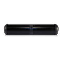
FALCON XL
Mounting height: 8 ft
23 ft 16 ft 11.5 ft 8 ft
3 3 3 3
4 4 4 4
5 5 5 4
6 6 6 5
15
°
30°
45°
> 45°
ft. 6.5 3 0 3 6.5
26 23 19.5 16.5 13 10 6.5 3 ft
FALCON
Mounting height: 16 ft
ft. 6.5 3 0 3 6.5
26 23 19.5 16.5 13 10 6.5 3 ft
FALCON
Mounting height: 11.5 ft
75.5678.04 20111104 Page 3 of 5
COM
NO
NC
12-24 V
AC-DC
Red
Black
White
Green
Yellow
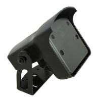
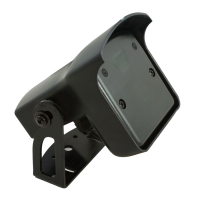
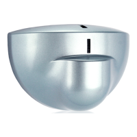
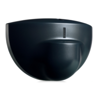
Position the sensor on the
bracket and fasten the screws
rmly.
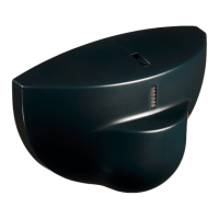
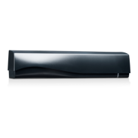
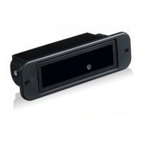
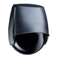
MOUNTING & WIRING
Adjust the angle of the sensor to position the detection eld.
Remove the bracket from
the sensor. Drill 2 holes
accordingly. Ax the bracket
rmly.
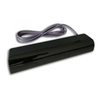
Connect the wires to the door
controller. Choose between
NO and NC contact.
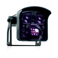
DETECTION FIELD
ADJUSTMENTS
Adjust the eld size with the remote
control or the push buttons.
All detection eld dimensions were measured in optimal conditions and with eld size value 9.
CEILING
WALL
Choose the right detection lter for your application with the remote control or the push buttons:
Value recommendations according to angle and height:
Detection of all targets
(pedestrians and parallel trafc are detected)
1 = no specic lter
2 = lter against disturbances
(recommended in case of vibrations,
rain etc.)
Detection only of vehicles moving towards the sensor*
(pedestrians and parallel trafc are not detected + disturbances are ltered)
* The vehicle detection lter increases the response time of the sensor.
DETECTION FILTER - PEDESTRIAN REJECTION - VEHICLE DETECTION
Always check if the chosen value is
optimal for the application. The
object approach angle, speed, size
and nature can inuence it’s
detection.