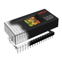
IPC@CHIP - SC12
Hardware Manual v1.1 [05.11.2002]
©BECK IPC GmbH page 10 of 28
4.5 Timer
Timer can be clocked internally or externally. Maximum frequency is 5MHz. If timer will be clocked
internally timer out pin (TMROUT) may be used. External clock at Input and output at the same time
with same timer is not possible.
Pin Name Type Function
TMRIN[0..1] I
Timer Input (input, edge-sensitive)
These pins supply a clock or control signal to the internal microcontroller
timer 0 and 1. After internally synchronizing a Low-to-High transition on
TMRIN, the microcontroller increments the corresponding timer. TMRIN
must be tied High if not being used. When PIO is enabled, TMRIN is pulled
High internally.
TMRIN0 is driven internally by INT2/PWD when pulse width demodulation
mode is enabled. The TMRIN0 pin can be used as a PIO when pulse width
demodulation mode is enabled.
TMROUT[0..1] O
Timer Output (output)
These pins supplies the system with either a single pulse or a continuous
waveform with a programmable duty cycle. TMROUT is floated during a bus
hold or reset.
4.6 10Base-T Interface
Pin Name Type Function
TPTX[+,-] O
Twisted Pair Driver (outputs)
These two outputs provide the TP drivers with pre-distortion capability
TPRX[+,-] I
Twisted Pair Receive (inputs).
A differential receiver tied to the receive transformer pair of the twisted-pair
wire.
The receive pair of the twisted-pair medium is driven with 10 Mbits/s
Manchester-encoded data
LINK LED O
Link and Traffic LED Driver (output)
If TP is LINK-pass, this pin outputs 3V in sink-mode.
This pin will output 5V, generated as an open-collector Hi mode for 50ms to
indicate the presence of traffic on the network. Note that this pin is not able
to source any current !
Please refer also to the schematic in chapter 10.2 Link LED / RESET.
4.7 Asynchronous Serial Ports
All asynchronous port pins are TTL level. To provide RS232 or RS485 level external drivers must be
connected (like MAX232). Following modes can be provided:
Full-Duplex Operation with 7-bit or 8-bit, odd, even or no parity. Error detection is possible with parity
errors, framing errors, overrun errors and break character recognition. Hardware handshaking (Clear-
to-send CTS and Request-to-send RTS) is possible.
To get a definite baud rate a baud rate divider must be provided.
A general formula for the baud rate divisor is:
BAUDDIV = (20 000 000 / (16 x Baud Rate))
The maximum baud rate is achieved by setting BAUDDIV=0001h. This results in a baud rate of
1250 Kbit. A BAUDDIV setting of zero results in no transmission or reception of data.
The serial port receiver can tolerate a 3.0% overspeed and 2.5% underspeed baud rate deviance.
The two ports can operate at different rates.

 Loading...