IPC@CHIP - SC12
Hardware Manual v1.1 [05.11.2002]
©BECK IPC GmbH page 6 of 28
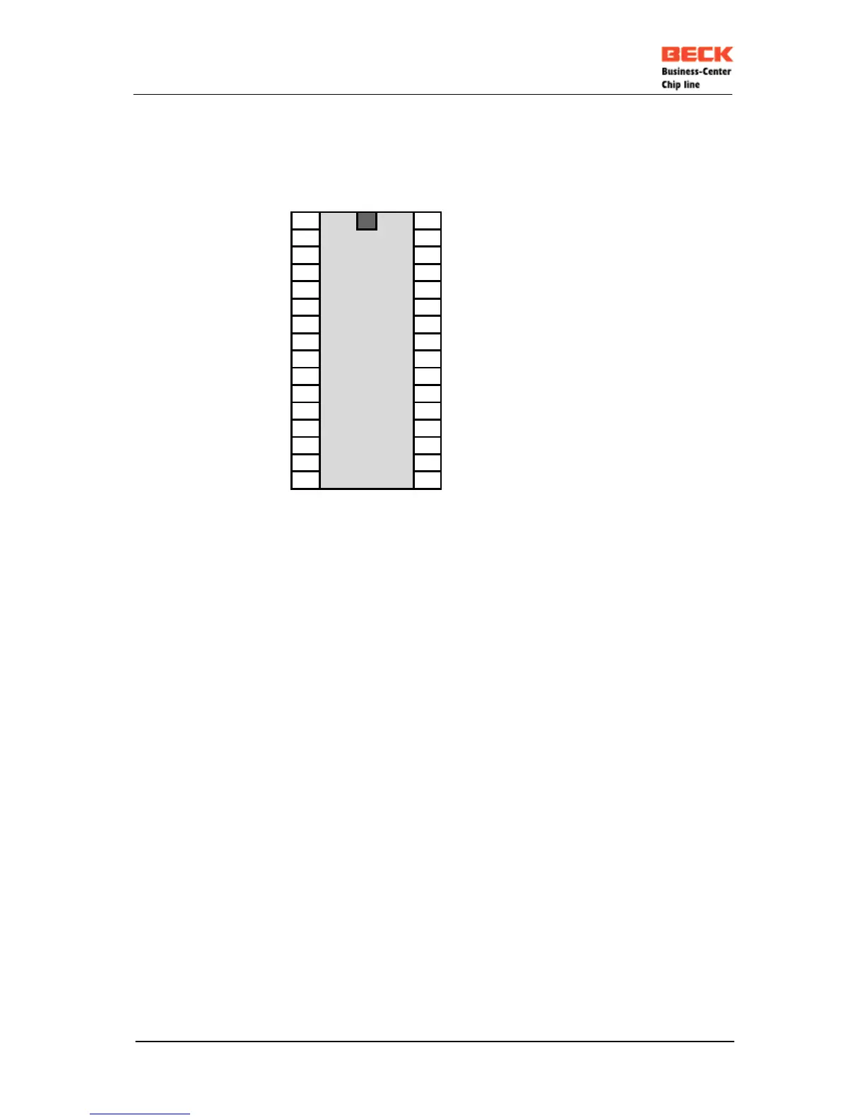
3. PIN CONFIGURATION
PIO7 / RXD0
1 32
VCC
PIO8 / TXD0
2 31
(I2C_SCL)* / DRQ1 / INT6 / PIO0
PIO9 / CTS0
3 30
(I2C_SDA)* / DRQ0 / INT5 / PIO1
PIO10 / RTS0
4 29
A2 / PCS6# / PIO2
PIO11 / TXD1
5 28
A1 / PCS5# / TMRIN1 / TMROUT1 / PIO3
PIO12 / INT3 / RXD1
6
IPC@CHIP
27
A0 / PCS1# / TMRIN0 / PIO4
PIO13 / INT0 / TMROUT0
7 26
RTS1 / PCS3# / INT4 / PIO5
AD0
8 25
CTS1 / PCS2# / INT2 / PWD / INTA# / PIO6
AD1
9 24
ALE / PCS0#
AD2
10 23
WR#
AD3
11 22
RD#
AD4
12 21
TPRX-
AD5
13 20
TPRX+
AD6
14 19
TPTX-
AD7
15 18
TPTX+
GND
16 17
RESET# / NMI / LINK_LED
* any other PIO pin may be assigned for use I²C signal by software
Locate decoupling capacitors as close to VCC Pin as physically possible.