IPC@CHIP - SC12
Hardware Manual v1.1 [05.11.2002]
©BECK IPC GmbH page 24 of 28
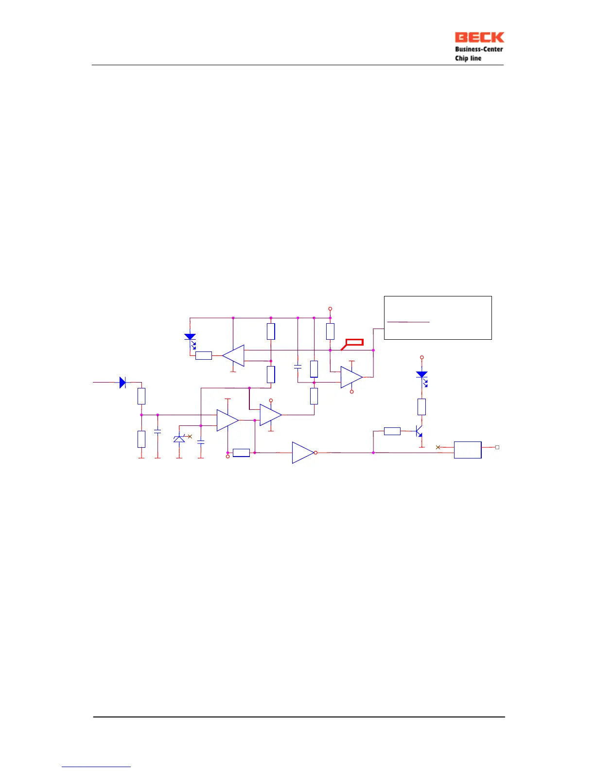
10. APPLICATION EXAMPLES
The following pages contain schematics showing the IPC@CHIP family microcontroller gives you
suggestions, how to handle the multi-function pin 17 RESET# / NMI / LINK-LED and how
to expand the SC12.
10.1 NMI / Reset-in / Link-LED
R188
R187
22k
1% !
R9
100k
The LM339 limits U17 to
approx. 4V
+
-
IC45B
LM339
5
4
2
3
12
R147
4k7
+
-
IC45D
LM339
11
10
13
3
12
GND
VCC
C11
0.1uF
3.32V
R147 is for understanding the circuitry only. The SC12 has
already build in a 1k Ohm pullup resistor.
R182
390R
IC10B
74HCT14
3 4
External sample circuitry /Reset + NMI + Link LED
R197
27k
+
-
IC45A
LM339
7
6
1
3
12
LED1
LED3mm
R12
390R
2,5V
LED2
LED3mm
GND
R198
10k
1% !
R11
20k
INT24V
D39
LL4148
C11470p
GND
R199
22k
VCC
C64
0.1uF
Q8
BC817-25L_1
RESET#
GND
IC8
NC7S14P5X
1
2
4
NC
IN