IPC@CHIP - SC12
Hardware Manual v1.1 [05.11.2002]
©BECK IPC GmbH page 14 of 28
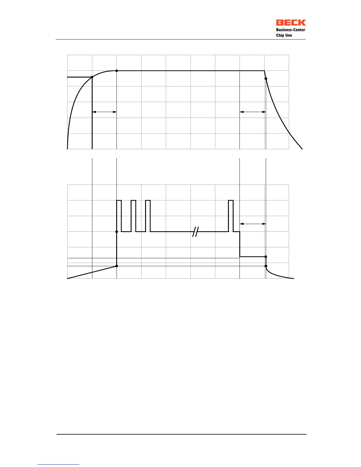
V
CC
(V)
5
4
3
2
1
200 400 600 800 1000 1200 1400 1600
t
REM
t
on/off
(ms)
t
Power OK
t
REM
=Time to save the retentive data
e. g. 1 kByte = 120 ms
2 kByte = 200 ms
t
Power OK
= max. 200 ms
V
CC
(V)
5
4
3
2
1
200 400 600 800 1000 1200 1400 1600
t
on/off
(ms)
Power up & power down sequence
4,7 V
5 V
NMI reset LILED sequence
4,65 V
t
REM
1,4 V
0,8 V
RESET
NMI
LINK
LINK
80 ms Link pause
3,0 V
Traffic
50 ms traffic imp.
0,8 V
To realize time to save the retentive data keep Pin 17 above 0,8V for t
REM
with external capacitors. If
Pin 17 goes below 0,8V IPC@CHIP will be in reset state.
If VCC goes below 4,65V IPC@CHIP will be in reset state and Pin 17 goes below 1,3V until Voltage
comes back.
Note: Retentive data must be one block.
If it is not, it takes more time to save.