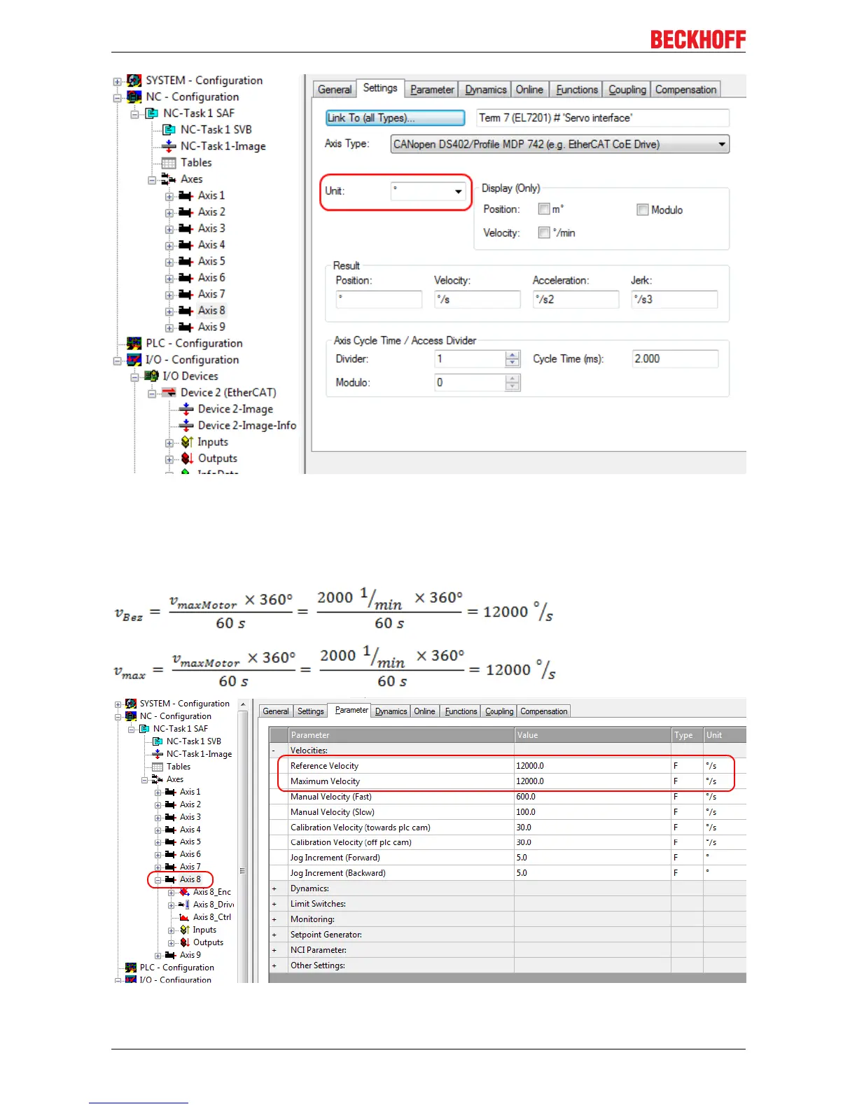
Home
Beckhoff
Servo Drives
EL7201-0010
Beckhoff EL7201-0010 User Manual
4
of 1
of 1 rating
208 pages
Give review
Manual
Specs
To Next Page
To Next Page
To Previous Page
To Previous Page
Loading...
Commissioning
Fig.122:
Definition of the unit
Selecting the maximum velocity
The
maximum permitted velocity
is calculated based on the maximum motor speed (name plate) and the
distance, in this case in relation to 360° per second.
Fig.123:
Adjusting the reference velocity
EL72x1-0010
98
Version: 2.0
97
99
Table of Contents
1 Product Overview Servomotor Terminal
4
Default Chapter
3
Product Overview Servomotor Terminal
3
Table of Contents
4
2 Foreword
6
Notes on the Documentation
6
Safety Instructions
7
Documentation Issue Status
8
Version Identification of Ethercat Devices
8
Fig. 1 EL5021 el Terminal, Standard IP20 IO Device with Batch Number and Revision ID (Since 2014/01)
10
Fig. 2 EK1100 Ethercat Coupler, Standard IP20 IO Device with Batch Number
10
Fig. 3 CU2016 Switch with Batch Number
10
El72X1
10
Fig. 4 EL3202-0020 with Batch Numbers 26131006 and Unique D-Number 204418
11
Fig. 5 EP1258-00001 IP67 Ethercat Box with Batch Number 22090101 and Serial Number 158102
11
Fig. 6 EP1908-0002 IP76 Ethercat Safety Box with Batch Number 071201FF and Serial Number 00346070
11
Fig. 7 EL2904 IP20 Safety Terminal with Batch Number/Date Code 50110302 and Serial Number 00331701
11
3 Product Overview
12
Introduction
12
Fig. 8 EL7201
12
Fig. 9 EL7211
12
Technical Data
14
Technology
14
Fig. 10: Three Synchronous Motor Coils, each Offset by 120
15
Start
17
Fig. 11 Limitation to the Rated Motor Current
17
4 Basics Communication
18
Ethercat Basics
18
Ethercat Cabling - Wire-Bound
18
General Notes for Setting the Watchdog
19
Fig. 12 System Manager Current Calculation
19
Fig. 13 Ethercat Tab -> Advanced Settings -> Behavior -> Watchdog
20
Ethercat State Machine
21
Fig. 14 States of the Ethercat State Machine
22
Coe Interface
23
Fig. 15 "Coe Online " Tab
24
Fig. 16 Startup List in the Twincat System Manager
25
Fig. 17 Offline List
26
Fig. 18 Online List
26
Distributed Clock
28
5 Installation
29
Installation on Mounting Rails
29
Fig. 19 Attaching on Mounting Rail
29
Fig. 20 Disassembling of Terminal
30
Installation Instructions for Enhanced Mechanical Load Capacity
31
Fig. 21 Power Contact on Left Side
31
Connection System
32
Fig. 22 Standard Wiring
32
Fig. 23 Pluggable Wiring
33
Fig. 24 High Density Terminals
34
Fig. 25 Mounting a Cable on a Terminal Connection
34
Mounting of Passive Terminals
35
Fig. 26 Correct Configuration
35
Fig. 27 Incorrect Configuration
35
Installation Positions
36
Fig. 28 Recommended Distances for Standard Installation Position
36
Shielding Concept
37
Fig. 29 Other Installation Positions
37
Notes on Current Measurements Using Hall Sensors
38
Fig. 30 Shield Busbar
38
Fig. 31 Shield Connection
38
El72X1-0010 - Leds and Connection
40
Fig. 33 EL7201-0010 - Leds
40
Fig. 34 EL7201-0010 - Connection
41
Fig. 35 EL7211-0010 - Leds
41
Fig. 36 EL7211-0010 - Connection
43
6 Commissioning
44
Twincat 2.1X
44
Installation of the Twincat Real-Time Driver
44
Fig. 37 System Manager Option
44
Fig. 38 Overview of Network Interfaces
44
Fig. 39 Ethercat Device Properties
44
Fig. 40 Windows Properties of the Network Interface
45
Fig. 41 Incorrect Driver Settings for the Ethernet Port
46
Fig. 42 TCP/IP Setting for the Ethernet Port
47
Notes Regarding ESI Device Description
48
Offline Configuration Creation (Master: Twincat 2.X)
52
Online Configuration Creation 'Scanning' (Master: Twincat 2.X)
58
Ethercat Slave Process Data Settings
67
General Notes - Ethercat Slave Application
68
Configuration by Means of the Twincat System Manager
77
Start-Up and Parameter Configuration
85
Integration into the NC Configuration
85
Settings with the Drive Manager
88
Settings in the Coe Register
93
NC Settings
97
Application Example
104
Fig. 134 Changing the PLC Path
106
Fig. 135 Required Libraries
106
Fig. 136 Global Variables
107
Fig. 137 Local Variables
107
Fig. 138 Program Code
108
Commissioning Without NC, Status Word/Control Word
109
Fig. 139 Visualization
109
Fig. 140 DS402 State Machine
110
Settings for the Automatic Configuration
112
Fig. 141 Flow Chart for the Automatic Configuration
113
Configuring the Limit Switch
114
Fig. 142 Pull-Down Menu for Activating End Position Monitoring
114
Homing
115
Fig. 143 Online Homing in the NC
115
Fig. 144 Configuration of the Mc_Home Block
116
Fig. 145 Extraction from the Functional Description for Mc_Home
116
Fig. 146 Selection of the Reference Modes in the NC
117
Fig. 147 Setting the Reference Velocity
117
Touch Probe
118
Fig. 148 Touch Probe Inputs
119
Fig. 149 Touch Probe Outputs
120
Modes of Operation
121
Overview
121
Csv
121
Fig. 150 Selection of the Mode of Operation
122
Fig. 151 Selecting a Predefined PDO Assignment
123
Fig. 152 Set Enables
124
Fig. 153 Torque Specification
124
Cst
125
Fig. 154 Selection of the Mode of Operation
125
Fig. 155 Selecting a Predefined PDO Assignment
126
Fig. 156 Set Enables
127
Cstca
128
Fig. 157 Torque Specification
128
Fig. 158 Selection of the Mode of Operation
129
Fig. 159 Selecting a Predefined PDO Assignment
130
Fig. 160 Set Enables
131
Csp
132
Fig. 161 Specification of Torque and Commutation Angle
132
Fig. 162 Selection of the Mode of Operation
133
Fig. 163 Selecting a Predefined PDO Assignment
134
Fig. 164 Set Enables
135
Fig. 165 Position Specification
136
Profile MDP 742 or DS 402
137
MDP742 Process Data
137
Fig. 167 Following Error over Time
137
Fig. 168 Process Data Tab SM2, El72X1-0010 (Default)
138
Fig. 169 Process Data Tab SM3, El72X1-0010 (Default)
139
DS402 Process Data
141
Fig. 170 Process Data Tab - Predefined PDO Assignment, El72X1-0010
141
Fig. 171 Process Data Tab SM2, El72X1-0010 (Default)
142
Fig. 172 Process Data Tab SM3, El72X1-0010 (Default)
143
Fig. 173 Process Data Tab - Predefined PDO Assignment, El72X1-0010
145
7 El72X1-0010-DS402 - Object Description and Parameterization
146
Configuration Data
147
Configuration Data (Vendor-Specific)
150
Command Object
150
Input/Output Data
150
Information / Diagnosis Data
155
Standard Objects
158
8 El72X1-0010-MDP742 - Object Description and Parameterization
165
Restore Object
165
Configuration Data
165
Fig. 32 Note
165
Fig. 166 Following Error Window
167
Configuration Data (Vendor-Specific)
170
Command Object
170
Input Data
170
Output Data
172
Information / Diagnosis Data
174
Standard Objects
177
9 Error Correction
186
Diagnose - Diag Messages
186
Fig. 174 Diagmessages in the Coe
187
Fig. 175 Implementation of the Diagmessage System in the Twincat System Manager
187
10 Appendix
191
Firmware Compatibility
191
Ethercat al Status Codes
192
Firmware Update El/Es/Em/Epxxxx
192
Fig. 176 Device Identifier Consisting of Name EL3204-0000 and Revision -0016
193
Fig. 177 Scan the Subordinate Field by Right-Clicking on the Ethercat Device in Config/Freerun Mode 193 Fig. 178 Configuration Is Identical
194
Fig. 179 Change Dialog
194
Restoring the Delivery State
202
Support and Service
203
List of Illustration
204
4
Based on 1 rating
Ask a question
Give review
Questions and Answers:
Need help?
Do you have a question about the Beckhoff EL7201-0010 and is the answer not in the manual?
Ask a question
Beckhoff EL7201-0010 Specifications
General
Brand
Beckhoff
Model
EL7201-0010
Category
Servo Drives
Language
English
Related product manuals
Beckhoff AX8000
246 pages
Beckhoff AX5000 Series
49 pages
Beckhoff AX5203
49 pages
Beckhoff AX5206
49 pages
Beckhoff AX5103
49 pages
Beckhoff AX5112
49 pages
Beckhoff AX5118
49 pages
Beckhoff AX5140
49 pages
Beckhoff AX5106
49 pages