Installation
Connection
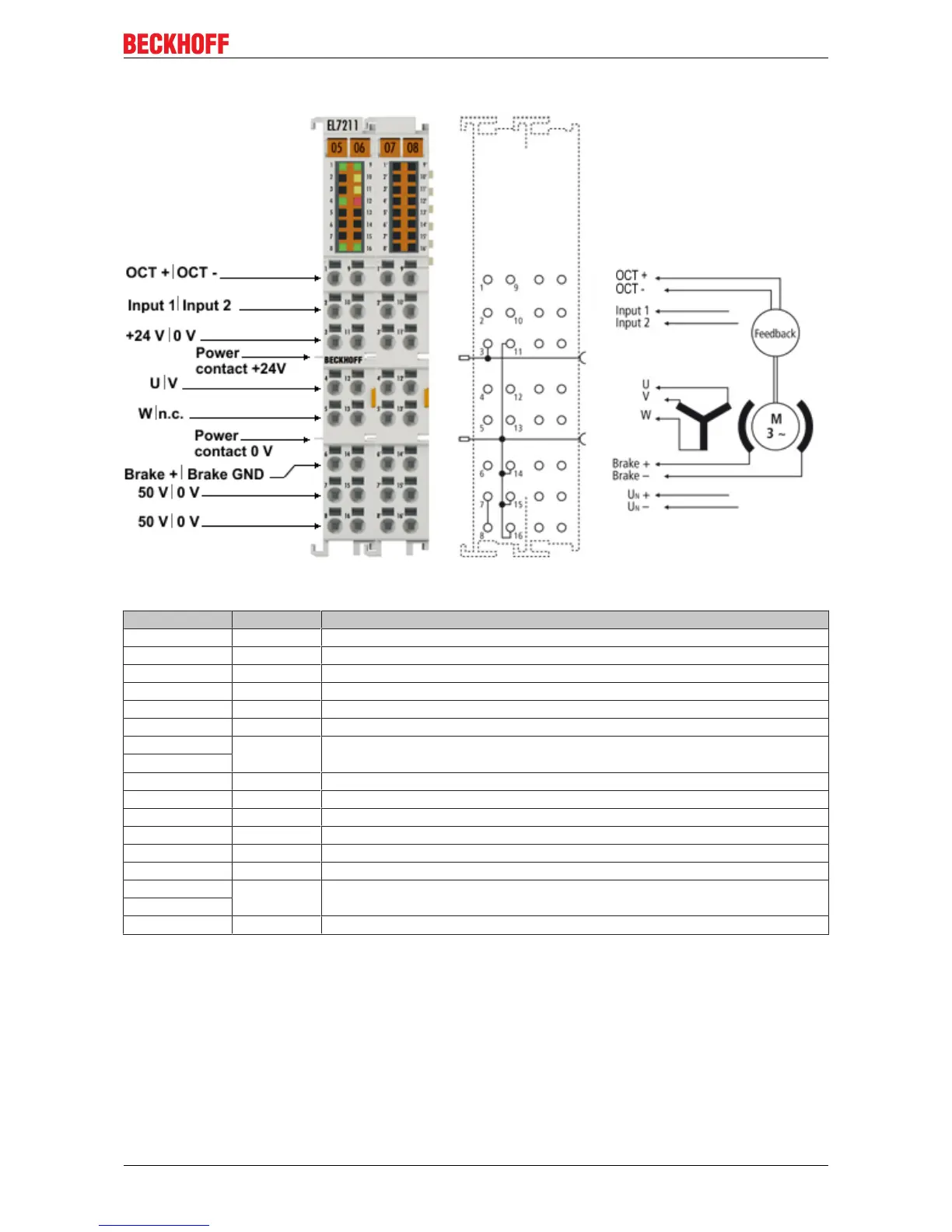
Fig.36: EL7211-0010 - Connection
Terminal point Name Comment
1 OCT + Positive input of the absolute feedback
2 Input 1 Digital input 1
3 +24 V Power contact +24 V
4 U Motor phase U
5 W Motor phase W
6 Brake + Motor brake +
7 50V DC link supply + (8...50 V)
8
9 OCT - Negative input of the absolute feedback
10 Input 2 Digital input 2
11 0V Power contact 0 V
12 V Motor phase V
13 n.c. not connected
14 Brake GND Motor brake 0V
15 0V DC link 0V supply
16
1' - 16' n.c.
EL72x1-0010 43Version: 2.0