27 PROTON User Manual
12.6 Low Frequency Oscillators
LFO 1 trigger and LFO 2 trigger, which cause the LFOs 1-shot and
retrigger to occur if selected when a suitable voltage trigger is
received (any voltage over 0 V will usually work); LFO 1 rate CV;
LFO 2 rate CV; LFO 1 shape CV; LFO 2 shape CV.
12.7 Envelope Generators
ADSR 1 gate/trigger; ADSR 2 gate/trigger; ASR 1 gate/trigger; ASR
2 gate/trigger.
12.8 Attenuverters
Attenuverter 1 in; attenuverter 2 in.
12.9 Multiple In
Allows an signal or voltage to be split and fed to two outputs on
the Out patchbay.
12.10 CV Mix
Input 1; input 2.
12.11 Assign In
Assignable CV input which can be set to feed either nothing
(default), osc 1, osc 2, osc 1 & 2, VCF 1, VCF 2 or VCF 1 & 2. This can
be set up using the SynthTribe app, or through the second panel by
pressing and holding the wavefolder mode button for two seconds
until it ashes then using the LFO encoder to scroll through the
options. Pressing the LFO shift button allows the encoder to
be used to set the depth from 0% to 100%. Pressing the mode
button again exits second panel.
12.12 Sum
Sum A; sum B where two CVs are summed together a fed to the
sum out socket on the Out patchbay.
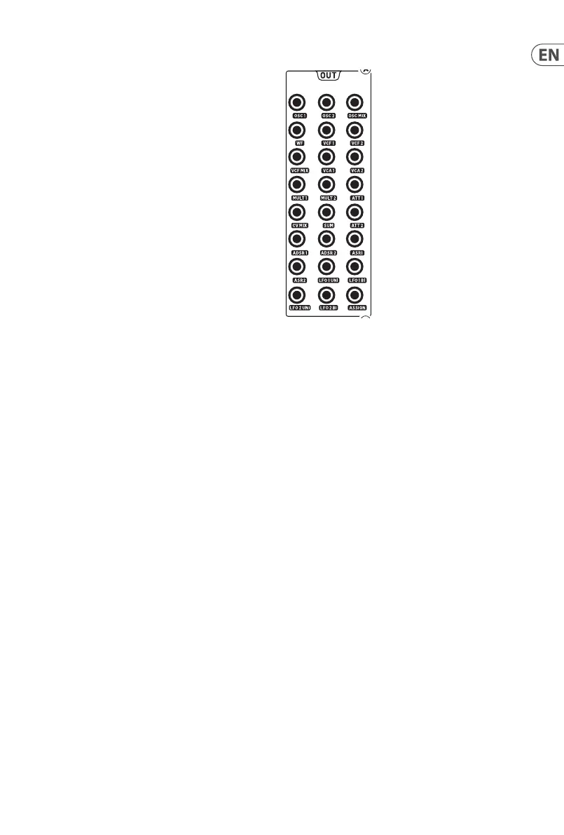
13. Out Patchbay
The Proton features a twenty four output patchbay, which allows
signals and control voltages to be routed to external processors,
orre-routed internally. Taking a feed from the Out patchbay will
not aect internal routing, unless specically noted.
13.1 Oscillators
Osc 1; Osc 2; Osc mix – audio feeds from the oscillators.
13.2 Wavefolder
Audio feed from the wavefolder output.
13.3 Filters
VCF 1; VCF 2; VCF mix – audio feeds from the VCFs.
13.4 Voltage Controller Ampliers
VCA 1; VCA 2 – audio feeds from the VCAs.
13.5 Multiples
Multiple 1; multiple 2 – split of a signal or CV fed into the multiple
in on the In patchbay. If there is no cable plugged into Multiple In
then Multiples 1 and 2 can be assigned using SynthTribe.
13.6 Attenuverters
Attenuverter 1; attenuverter 2 – outputs from the attenuverters
fed from the In patchbay. If there is no input on attenuverter 1
then the output will be ADSR 1. If there is no input on attenuverter
2 then the output will be LFO 1 (bipolar).