13
4.6.
Control Terminal Wiring
• All analog signal cables should be suitably shielded. Twisted pair cables are recommended.
• Power and Control Signal cables should be routed separately where possible, and must not be routed parallel to each other.
• Signal levels of different voltages e.g. 24 Volt DC and 110 Volt AC, should not be routed in the same cable.
• Maximum control terminal tightening torque is 0.5Nm.
• Control Cable entry conductor size: 0.05 – 2.5mm
2
/ 30 – 12 AWG.
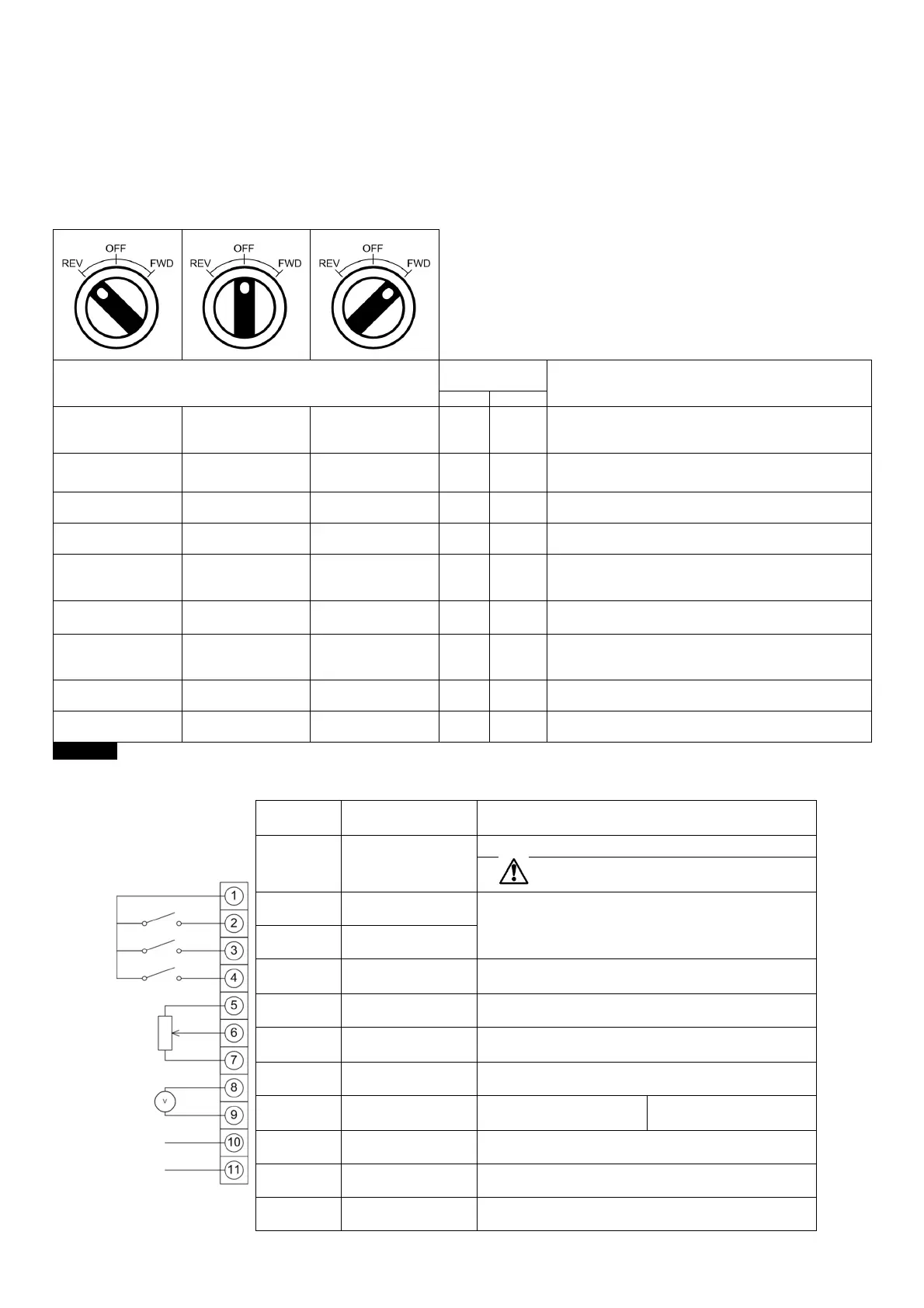
4.7. Using the REV/0/FWD Selector Switch (Switched Version Only)
By adjusting the parameter settings the BFI-E3 can be configured for multiple applications and not just for Forward or Reverse.
This could typically be for Hand/Off/Auto applications (also known and Local/Remote) for HVAC and pumping industries.
Switch Position
Set
Notes
Run Reverse STOP Run Forward 0 0
Factory Default Configuration
Run Forward or Reverse with speed controlled from the
Local POT
STOP STOP Run Forward 0 5,7
Run forward with speed controlled form the local POT
Run Reverse - disabled
Preset Speed 1 STOP Run Forward 0 1
Run Forward with speed controlled from the Local POT
Preset Speed 1 provides a ‘Jog’ Speed set in P-20
Run Reverse STOP Run Forward 0 6, 8
Run Forward or Reverse with spee
Local POT
Run in Auto STOP Run in Hand 0 4
Speed controlled from the Local POT
Run in Auto 0 Speed controlled using Analog input 2 e.g.
from PLC with 4-20mA signal.
Run in Speed Control STOP Run in PI Control 5 1
In Speed Control the speed is controlled from the Local POT
In PI Control, Local POT controls PI set point
Run in Preset Speed
Control
STOP Run in PI Control 5
4,5,
8..12
In Preset Speed Control, P
In PI Control, POT can control the PI set point
(P-44=1)
Run in Hand STOP Run in Auto 3 6
speed controlled from the Local POT
Auto – Speed Reference from Modbus
Run in Hand STOP Run in Auto 3 3
Speed reference from Preset Speed 1 (P
Auto – Speed Reference from Modbus
NOTE To be able to adjust parameter P-15, extended menu access must be set in P-14 (default value is 101)
4.8. Control Terminal Connections
Default Connections Control
Terminal
Signal Description
1 +24Vdc User Output
+24Vdc user output, 100mA.
Do not connect an external voltage source to
this terminal.
2 Digital Input 1
Positive logic
“Logic 1” input voltage range: 8V … 30V DC
“Logic 0” input voltage range: 0V … 4V DC
3 Digital Input 2
4
Digital Input 3 /
Analog Input 2
Digital: 8 to 30V
Analog: 0 to 10V, 0 to 20mA or 4 to 20mA
5 +10V User Output +10V, 10mA, 1kΩ minimum
6
Analog Input 1 /
Digital Input 4
Analog: 0 to 10V, 0 to 20mA or 4 to 20mA
Digital: 8 to 30V
7 0V 0 Volt Common, internally connected to terminal 9
8
Analog Output /
Digital Output
Analog: 0 to 10V,
Digital: 0 to 24V
20mA maximum
9 0V 0 Volt Common, internally connected to terminal 7
10 Relay Common
11 Relay NO Contact Contact 250Vac, 6A / 30Vdc, 5A