23
7. Analog and Digital Input Macro Configurations
7.1. Overview
BFI-E3 uses a Macro approach to simplify the configuration of the Analog and Digital Inputs. There are two key parameters which determine
the input functions and drive behaviour:-
• P-12 – Selects the main drive control source and determines how the output frequency of the drive is primarily controlled.
• P-15 – Assigns the Macro function to the analog and digital inputs.
Additional parameters can then be used to further adapt the settings, e.g.
• P-16 – Used to select the format of the analog signal to be connected to analog input 1, e.g. 0 – 10 Volt, 4 – 20mA
• P-30 – Determines whether the drive should automatically start following a power on if the Enable Input is present
• P-31 – When Keypad Mode is selected, determines at what output frequency / speed the drive should start following the enable
command, and also whether the keypad start key must be pressed or if the Enable input alone should start the drive.
• P-47 – Used to select the format of the analog signal to be connected to analog input 2, e.g. 0 – 10 Volt, 4 – 20mA
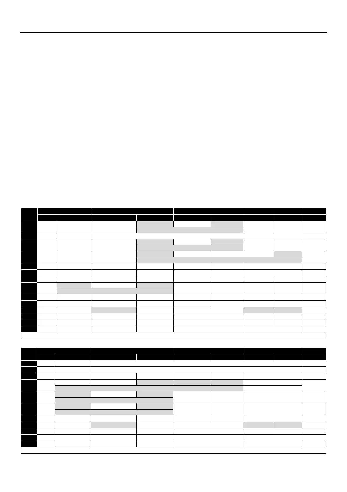
The diagrams below provide an overview of the functions of each terminal macro function, and a simplified connection diagram for each.
7.2. Macro Functions Guide Key
STOP / RUN Latched input, Close to Run, Open to Stop
Forward Rotation /Reverse Rotation Selects the direction of motor operation
AI1 REF Analog Input 1 is the selected speed reference
P-xx REF Speed setpoint from the selected preset speed
PR-REF Preset speeds P-20 – P-23 are used for the speed reference, selected according to other digital input
˄-FAST STOP (P-24)-˄ When both inputs are active simultaneously, the drive stops using Fast Stop Ramp Time P-24
E-TRIP External Trip input, which must be Normally Closed. When the input opens, the drive trips showing
E-trip
E-tripE-trip
E-trip or ptc-th
ptc-thptc-th
ptc-th depending on P-47 setting
(NO) Normally Open Contact, Momentarily Close to Start
(NC) Normally Closed Contact, momentary Open to Stop
7.3. Macro Functions - Keypad Mode (P-12 = 1 or 2)
-------------------------------------
-------------------------------
7.4. Macro Functions - Fieldbus Control Mode (P-12 = 3, 4, 7, 8 or 9)
FB REF (Fieldbus Speed Reference, Modbus RTU / CAN / Master