EasyManua.ls Logo

Beijer Electronics E3 - Macro Functions - Terminal Mode (P-12 = 0)

Beijer Electronics E3
32 pages
Print Icon
To Next Page IconTo Next Page
To Previous Page IconTo Previous Page
Loading...
24
7.5.
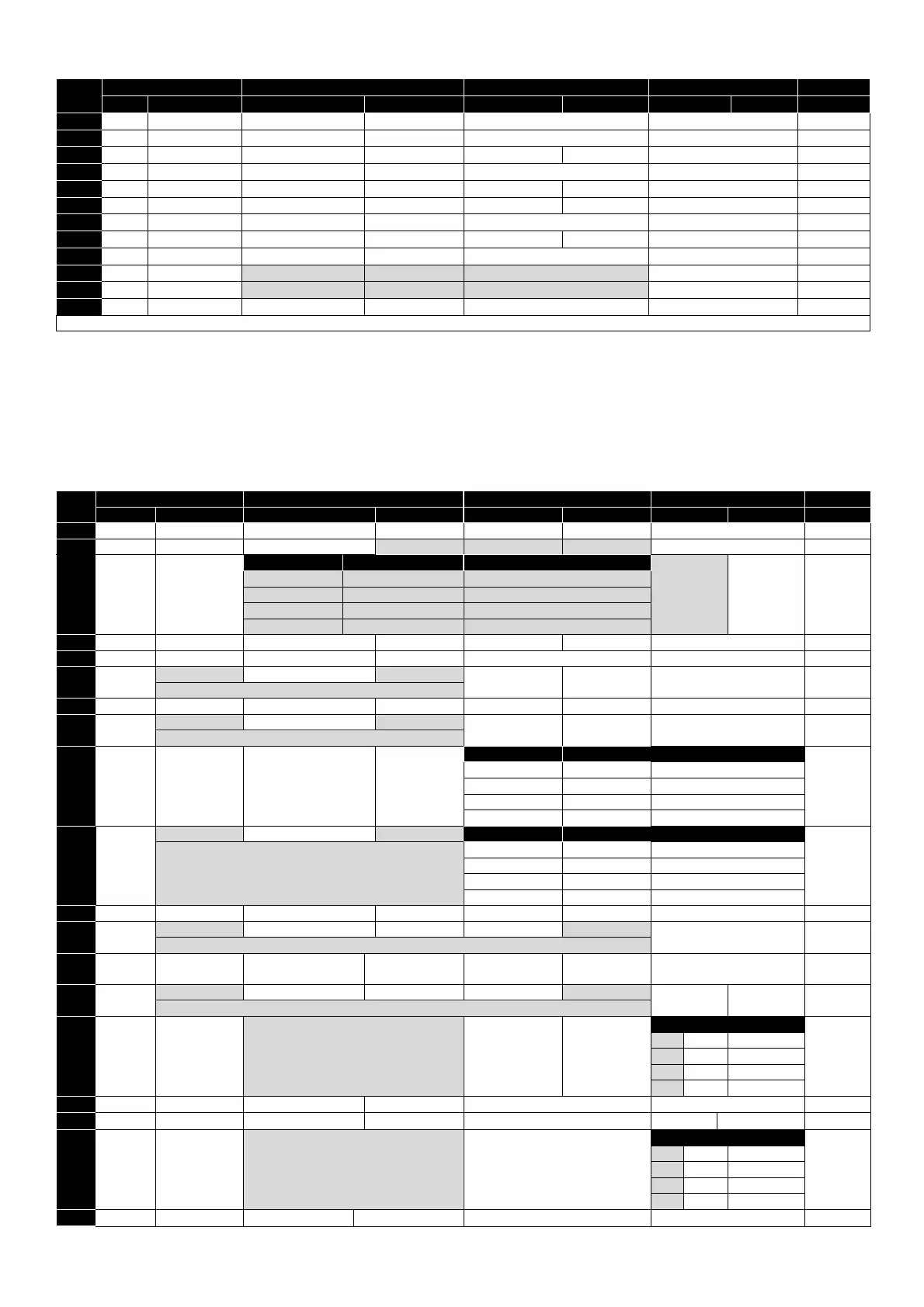
Macro Functions - User PI Control Mode (P-12 = 5 or 6)
P
-
15
DI1
DI2
DI3 / AI2
DI4 / AI1
Diagram
0
1
0
1
0
1
0
1
0
STOP
ENABLE
PI REF
P
-
20 REF
AI2
AI1
4
1
STOP
ENABLE
PI REF
AI1 REF
AI2 (PI FB)
AI1
4
3, 7
STOP
ENABLE
PI REF
P
-
20
E
-
TRIP
OK
AI1 (PI FB)
3
4
(NO)
START
(NC)
STOP
AI2 (PI FB)
AI1
12
5
(NO)
START
(NC)
STOP
PI REF
P
-
20 REF
AI1 (PI FB)
5
6
(NO)
START
(NC)
STOP
E
-
TRIP
OK
AI1 (PI FB)
8
STOP
RUN
FWD
REV
AI2 (PI FB)
AI1
4
14
STOP
RUN
-
-
E
-
TRIP
OK
AI1 (PI FB)
16
15
STOP
RUN
P
-
23 REF
PI REF
Fire Mode
AI1 (PI FB)
1
16
STOP
RUN
P
-
23 REF
P
-
21 REF
Fire Mode
AI1 (PI FB)
1
17
STOP
RUN
P
-
21 REF
P
-
23 REF
Fire Mode
AI1 (PI FB)
1
18
STOP
RUN
AI1 REF
PI R
EF
Fire Mode
AI1 (PI FB)
1
2,9,10,11,12,13 = 0
Fire Mode
ENABLE Hardware Enable Input. In Keypad Mode, P-31 determines whether the drive immediately starts, or the
keypad start key must be pressed. In other modes, this input must be present before the start signal via
the fieldbus interface
INC SPD Normally Open, Close the input to Increase the motor speed
DEC SPD Normally Open, Close input to Decrease motor speed
KPD REF Keypad Speed Reference selected
FB REF Selected speed reference from Fieldbus (Modbus RTU / CAN Open / Master depending on P-12 setting)
7.6. Macro Functions – Terminal Mode (P-12 = 0)
P
-
15
DI1
DI2
DI3 / AI2
DI4 / AI1
Diagram
0
1
0
1
0
1
0
1
0
STOP
RUN
FWD
REV
AI1 REF
P
-
20 REF
Analog Input AI1
1
1
STOP
RUN
AI1 REF
PR
-
REF
P
-
20
P
-
21
Analog Input AI1
1
2
STOP
RUN
DI2
DI3
PR
P
-
20
-
P
-
23
P
-
01
2
0
0
P
-
20
1
0
P
-
21
0
1
P
-
22
1
1
P
-
23
3
STOP
RUN
AI1
P
-
20 REF
E
-
TRIP
OK
Analog Input AI1
3
4
STOP
RUN
AI1
AI2
Analog Input AI2
Analog Input AI1
4
5
STOP
RUN
FWD
STOP
RUN REV
AI1
P
-
20 REF
Analog Input AI1
1
˄
-----------
FAST STOP (P
-
24)
------------
˄
6
STOP
RUN
FWD
REV
E
-
TRIP
OK
Analog Input AI1
3
7
STOP
RUN FWD
STOP
RUN REV
E
-
TRIP
OK
Analog Input AI1
3
˄
-----------
FAST STOP (P
-
24)
-----------
----
˄
8
STOP
RUN
FWD
REV
DI3
DI4
PR
2
0
0
P
-
20
1
0
P
-
21
0
1
P
-
22
1
1
P
-
23
9
STOP
START FWD
STOP
START REV
DI3
DI4
PR
2
˄
---------------
FAST STOP (P
-
24)
------------------
˄
0
0
P
-
20
1
0
P
-
21
0
1
P
-
22
1
1
P
-
23
10
(NO)
START
STOP
(NC)
AI1 REF
P
-
20 REF
Analog Input AI1
5
11
(NO)
START FWD
STOP
(NC)
(NO)
START REV
Analog Input AI1
6
˄
-----------------------------
FAST STOP (P
-
24)
---------------------------------------
------
˄
12
STOP
RUN
FAST STOP (P
-
24)
OK
AI1 REF
P
-
20 REF
Analog Input AI1
7
13
(NO)
START FWD
STOP
(NC)
(NO)
START REV
KPD REF
P
-
20 REF
13
˄
-------------------------
FAST STOP (P
-
24)
----------------------------------------
˄
14
STOP
RUN
DI2
E
-
TRIP
OK
DI2
DI4
PR
11
0
0
P
-
20
1
0
P
-
21
0
1
P
-
22
1
1
P
-
23
15
STOP
RUN
P
-
23 REF
AI1
Fire Mode
Analog Input AI1
1
16
STOP
RUN
P
-
23 REF
P
-
21 REF
Fire Mode
FWD
REV
2
17
STOP
RUN
DI2
Fire Mode
DI2
DI4
PR
2
0
0
P
-
20
1
0
P
-
21
0
1
P
-
22
1
1
P
-
23
18
STOP
RUN
FWD
REV
Fire Mode
Analog Input AI1
1

Table of Contents

Related product manuals