9
3.5.
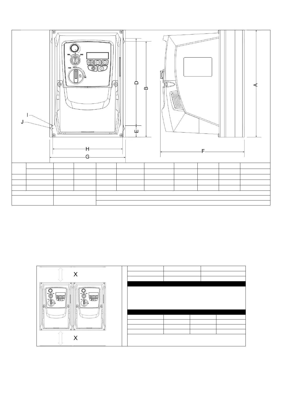
Mechanical Dimensions – IP66 Enclosed Units
Drive
Size
A / Height B D E F / Depth G / Width H I J
Weight
mm
mm
mm
mm
mm
mm
mm
mm
mm
kg
1
232 207 189 25.0 179 161 148.5 4.0 8.0 3,1
2
257 220 200 28.5 187 188 176.0 4.2 8.5 4,1
3
310 276.5 251.5 33.4 252 210 197.5 4.2 8.5 7,6
All Frame Sizes
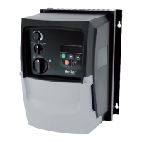
3.6. Guidelines for Mounting Enclosed Units
• Before mounting the drive, ensure that the chosen location meets the environmental condition requirements for the drive shown in
section 9.1
• The drive must be mounted vertically, on a suitable flat surface
• The minimum mounting clearances as shown in the table below must be observed
• The mounting site and chosen mountings should be sufficient to support the weight of the drives
• Using the drive as a template, or the dimensions shown below, mark the locations required for drilling
• Suitable cable glands to maintain the ingress protection of the drive are required. Gland holes for power and motor cables are pre-
moulded into the drive enclosure, recommended gland sizes are shown above. Gland holes for control cables may be cut as required
Typical drive heat losses are approximately 3% of operating load
conditions.
Above are guidelines only and the operating ambient temperature of the
drive MUST be maintained at all times.