VAV – Module NMV-D2M
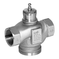
Practical tip – Quick setting
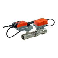
N-E2.1.1 Reference signal [w], Working range V’min ... V’max
Start point: DC 0.6 ... 30 V
Stop point: DC 2.6 ... 32 V
Range:
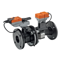
N-E2.1.2 Actual volumetric flow signal [U5]
Actual volumetric flow signal [U5], Working range 0...100% V’nom
Start point: DC 0.0 ... 8 V
Stop point: DC 2.0 ... 10 V
Range:
N-E2.1.3 Sensor connection
In bus mode (‘MP’ address 1...8) an active sensor or a switch can be
connected to the NMV-D2M reference input [w]. This input value can be
used in the higher level control system for VAV control, e.g. room tem-
perature or other applications. See 4. NMV-D2M Product Information for
further information.
- Connecting switches
In order to allow the NMV-D2M to evaluate the status of a connected
switch reliably the start point of the working range must be properly set
first:
Start point: DC 0.6 V It is essential for the Start Point to be
set to 0.6 V
Stop point: DC 10 V
Reference signal function [w]
in the V’min ... V’max control range
for controlling the NMV-
variable setting
Actual volumetric flow signal [U5]
corresponds to 0...100% V’nom
indicates the current actual value of volumetric flow