CC613 charge controller
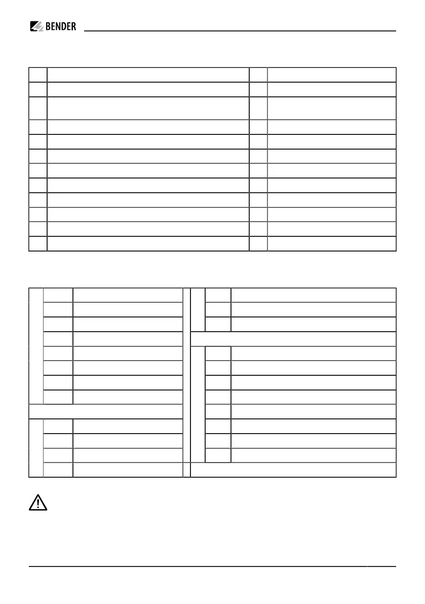
Legend
A Connection measuring current transformer (CT) m RCD type A
B 12 V supply, PE, Modbus meter, CP, PP n Supply voltage DC 12 V
C 2x USB type A (1, 2) o Measuring current transformer (CT) with
plug
D Connection Ethernet (ETH1) p Contactor
E Antenna socket 4G (only available for variants with 4G modem
1
) q Type 2 socket-outlet
F Configuration interface
G Micro SIM card slot (only available for variants with 4G modem
1
)
H Weld check, relay for contactor control rated for 230 V/4 A
I External Modbus (galvanic separation)
J Locking, control relay GPIO, optocoupler input
K Connection user interface (HMI) (not available with HEM-X2 variant)
L STATUS LED
1
Data gateways with 4G modem: CC613-ELM4PR-M and CC613-ELM4PR
Terminal assignment (depending on the variant)
0 V Input 0 V GND2 External Modbus GND (shield connected on one side)
+12 V Supply voltage +12 V B2 External Modbus B (galvanic separation)
PE Input PE
I
A2 External Modbus A (galvanic separation)
PE Input PE
B Mod. Modbus meter B In- Opto 1 In-: Optocoupler input 12 V negative
A Mod. Modbus meter A IN+ Opto 1 In+: Optocoupler input 12 V positive
CP Control Pilot A Actuator A: Locking actuator output negative
B
PP Proximity Pilot B Actuator B: Locking actuator output positive
HS2 Actuator HS2: Locking input actuator switch
WA Weld check input L1 HS1 Actuator HS1: Locking 12 V output actuator switch
23 Relay 23: Switching contact contactor 14 Relay 14: Relay contacts GPIO (12 V)
WB Weld check input N
J
13 Relay 13: Relay contacts GPIO (12 V)
H
24 Relay 24: Switching contact contactor
ADVICE
CAUTION! Switching contact contactor and weld check at terminal H are only suitable for mains
voltage (230 V)! Not permitted for SELV/PELV voltages.
CC613_D00381_07_M_XXEN/02.2023 15