12 iso685-x_D00022_11_Q_INTE/03.2021
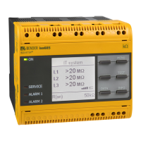
ISOMETER® iso685…
i
Das Profil „Leistungskreise“ ist für die meisten IT-
Systeme geeignet. Eine Beschreibung der Profile finden
Sie im Handbuch.
i
Bis der Inbetriebnahme-Assistent abgeschlos-sen ist,
sind die Relais abgefallen.
i
The profile „power circuits“ is suitable for most of the IT
systems. For a description of the profiles refer to the
manual.
i
The relays are de-energised until the commissioning
process is finished.
Werkseinstellungen
Ansprechwerte
Ansprechwert R
an1
(Alarm 1) ........................................................40 kΩ
Ansprechwert R
an2
(Alarm 2) ........................................................10 kΩ
Fehlerspeicher..................................................................................aus
Ankoppelüberwachung ....................................................................ein
Geräteprofil ............................................................... „Leistungskreise“
Art des zu überwachenden Netzes
Netzform ......................................................................................... 3AC
Zeitverhalten
Anlaufverzögerung T
Anlauf
..................................................................0 s
Schaltglieder
Relais 1
Arbeitsweise .............................................................. Ruhestrom (N/C)
Funktion 1 ..........................................................................Iso. Alarm 1
Funktion 2 ........................................................................................aus
Funktion 3 ....................................................................Anschlussfehler
Relais 2
Arbeitsweise .............................................................. Ruhestrom (N/C)
Funktion 1 ..........................................................................Iso. Alarm 2
Funktion 2 ......................................................................... Gerätefehler
Funktion 3 ....................................................................Anschlussfehler
Factory settings
Response values
Response value R
an1
(Alarm 1) ...................................................... 40 kΩ
Response value R
an2
(Alarm 2) ...................................................... 10 kΩ
Fault memory ...................................................................................off
Coupling monitoring .........................................................................on
Device profile ...............................................................„Power circuits“
Type of system to be monitored
System type ....................................................................................3AC
Time response
Start-up delay T
Anlauf
..........................................................................0 s
Switching elements
Relay 1
Operating principle .........................................................N/C operation
Function 1 .......................................................................... Ins. Alarm 1
Function 2 ........................................................................................aus
Function 3 ................................................................... Connection fault
Relay 2
Operating principle .........................................................N/C operation
Function 1 .......................................................................... Ins. Alarm 1
Function 2 .......................................................................... Device fault
Function 3 ................................................................... Connection fault
Der Alarm und seine Wirkung
Ursachen für eine Alarmmeldung
• Isolationsfehler: Isolationswiderstand unterschreitet
beide Ansprechwerte (LED ALARM 1, ALARM 2)
• Gerätefehler (LED SERVICE)
• Isolationsfehlersuche aktiv (iso685-x-P, PGH ON)
Gerät meldet Alarm bzw. Gerätefehler
• Display zeigt Fehler und Messwert an.
• Bei Alarm leuchten die zugehörigen LEDs.
• Alarmton ertönt intervallweise, wenn zugeordnet.
• Zugeordnete Alarmrelais schalten.
• Zugeordnete digitale Ausgänge schalten.
Alarmmeldungen zurücksetzen (Reset)
• Voraussetzung: Ursache für Alarmmeldung besteht
nicht mehr. Isolationswiderstand muss mindestens
25 % über dem Ansprechwert liegen.
• Wählen Sie: „RESET“ > „RESET“ > „OK“.
Alarm and its effect
Cause of the alarm
• Insulation fault: The insulation resistance is below
both response values (LED ALARM 1, ALARM 2)
• Device error (LED SERVICE)
• Active insulation fault location (iso685-x-P, PGH ON)
Device signals alarm or device error
• Display indicates error and measured value.
• In the event of an alarm the associated LEDs flash.
• A warning sound beeps at intervals, if assigned.
• Assigned alarm relays will switch.
• Assigned digital outputs will switch.
Reset alarm messages (Reset)
• Requirement: The cause of the alarm is no longer
present. The insulation resistance must be at least
25 % higher than the response value.
• Select: „RESET“ > „RESET“ > „OK“.

 Loading...


