ISOMETER® iso685…
iso685-x_D00022_11_Q_INTE/03.2021 7
Connection
Wire up the device according to the wiring diagram taking
account of the technical data. After connecting the device,
install the enclosed upper and lower terminal cover!
I
WarninG! Injury, fire and damage to property due
to a short circuit! When coupling the terminals
L1/+, L2, L3/- to the IT system ≤ 690 V to be monito-
red, devices for protection against a short-circuit
can be omitted according to IEC 60364-4-43:2008 or
DIN VDE 0100430 if the wiring is carried out in such
a way as to reduce the risk of a short-circuit to a
minimum. Pay attention to short-circuit proof and
earth-fault proof wiring.
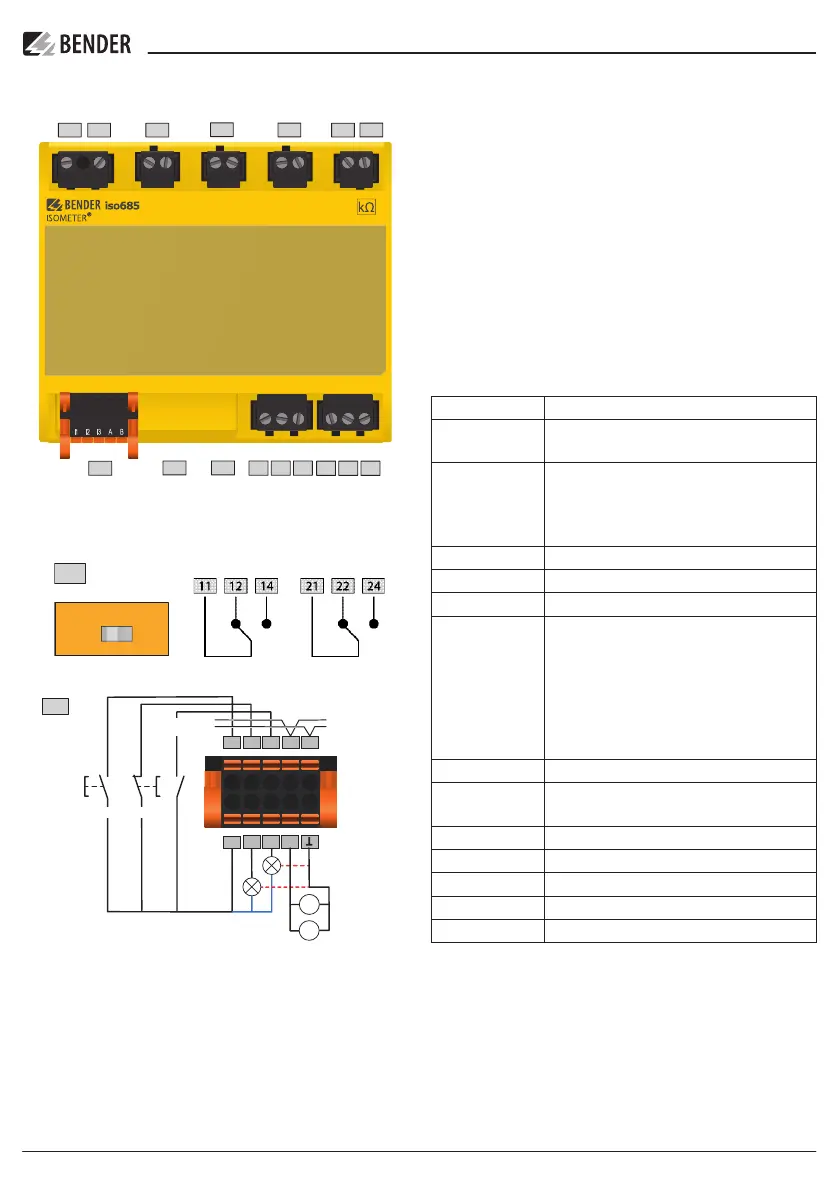
Legend to terminal diagrams
Terminal Connections
A1/+ A2/- ** Power supply,
U
s
= 24…240 V (50…400 Hz)
L1/+, L2, L3/- Connections to the system to be monitored
AC, 0…690 V
AC, 0…600 V für UL applications
DC, 0…1000 V
KE E Connection to ground
I1…I3 (X1) Configurable digital inputs (e.g. Test, Reset,…)
A, B (X1) Serial interface RS-485 (BS bus)
+ (X1) Supply voltage of the inputs and outputs I, Q and M.
Electrical overload protection. Automatic shutdown
in the event of a short circuit and transient
(resettable).
If the supply is via an external 24 V source, then
A1/+, A2/- must not be connected.
Q1, Q2 (X1) Configurable digital output
M+ (X1) Configurable analogue output (e.g. measuring
instrument)
(X1) Reference potential ground
RJ45 (ETH) Ethernet connector, webserver, modbus, IP
R Termination for the BS bus
11 12 14 Relay 1
21 22 24 Relay 2
i
** Provide line protection! According to DIN VDE 0100-
430, a line protection shall be provided for the supply
voltage
141211
242221
ETH R
X1
L1/+A2/–A1/+
OFF ON
R
RS-485
I1
I2
A
BI3
Q1
Q2
M+
+
high
active
low
active
V
A
Voltagemete
passive adjustable
TEST
RESET
Deactivate
Device
+24 V