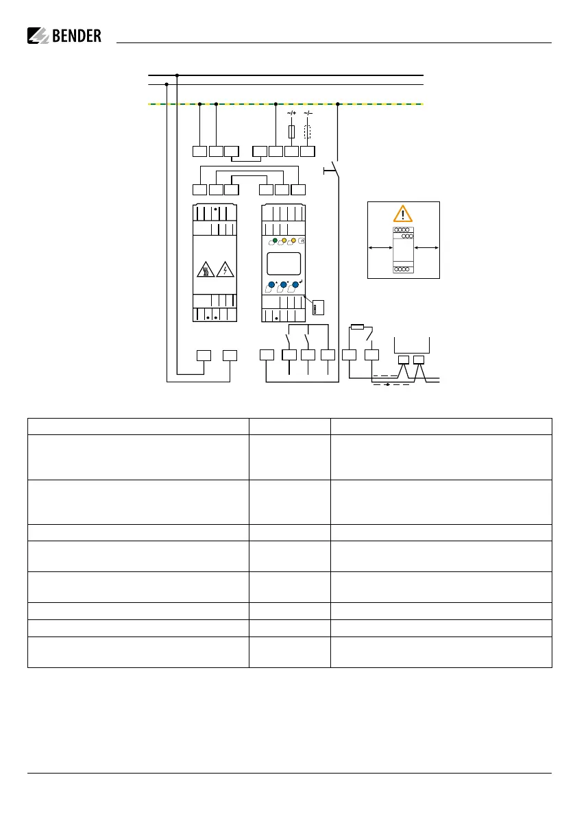
Anschlussbild
U
S
KE A1 A2
Test / Reset
Up
6 A6 A
DC +
DC -
PE
UpEE
GND AK2
AK1AK1GNDAK2
L2/-
L1/+
14 24
11
K1 K2
COM465IP
RS-485
A
B
R
T/R
AB
E
E
UP
AK2
AK1
GND
L1/+
L2/-
ON
AL1AL2
k
TR
MENU
R
on
o
14
24
11
A
T/R
B
AK1
AK2
GND
UP
KE
A2
A1
AGHxxx
30 mm
30 mm
Legende zum Anschlussbild
Anschlüsse Klemme/ Terminal Connections
Anschluss an die Versorgungsspannung U
s
über
Schmelzsicherung: Bei Versorgung aus IT-System beide
Leitungen absichern.*
A1, A2
Connection to the supply voltage U
s
via a fuse:
If supplied from an IT system, both lines have to be pro-
tected by a fuse.*
Jede Klemme jeweils separat an PE anschließen:
Gleichen Leitungsquerschnitt wie bei „A1“, „A2“ ver-
wenden.
E, E, KE
Connect each terminal separately to PE:
The same wire cross section as for „A1“, „A2“ is to be
used.
Anschluss an das zu überwachende IT-Netz L1/+, L2/– Connection to the IT system to be monitored
Klemmen des AGH420 mit den gleichnamigen Klemmen
des ISOMETER®s verbinden.
Up, AK1, GND, AK2
Connect the terminals of the AGH420 to the correspon-
ding terminals of the ISOMETER®.
Anschluss für externe kombinierte Test- und Reset-Taste
T/R
Connection for the external combined test and reset
button
Anschluss Alarmrelais „K1“ 11, 14 Connection to alarm relay „K1“
Anschluss Alarmrelais „K2“ 11, 24 Connection to alarm relay „K2“
RS-485-Kommunikationsschnittstelle mit zuschaltba-
rem Terminierungswiderstand
A, B
RS-485 communication interface with selectable ter-
minating resistance
Wiring diagram legend
i
* Für UL-Anwendungen:
Nur 60/75°C-Kupferleitungen verwenden! Die Ver-
sorgungsspannung U
s
ist bei UL- und CSA-Appli-
kationen zwingend über 5-A-Vorsicherungen zu-
zuführen.
Wiring diagram
ISOMETER® isoPV425
isoPV425_D00028_04_Q_DEEN/ 11.2022 3
i
* For UL applications:
Only use 60/75°C copper lines! For UL and CSA
applications, it is mandatory to use 5 A fuses for
the protection of the supply voltage Us.

 Loading...


