Technical data
()* = Factory settings
Insulation coordination acc. to IEC 60664-1/IEC 60664-3
Rated voltage ..........................................................................240 V
Overvoltage category ....................................................................III
Supply voltage
Supply voltage U
s
.................................................... AC 100…240 V
..................................................................................DC 24…240 V
Tolerance of U
s
........................................................... -30…+15 %
Frequency range U
s
........................................................ 47…63 Hz
Power consumption .................................................. ≤ 3 W, ≤ 9 VA
Monitored IT system
Nominal system voltage U
n
............................ 3(N)AC, AC 0…690 V
.................................................................................DC 0…1 000 V
Nominal system voltage according to UL508 ........AC/DC 0…600 V
Tolerance of U
n
...............................................AC +15 %, DC +10 %
Frequency range of U
n
............................................DC, 15…460 Hz
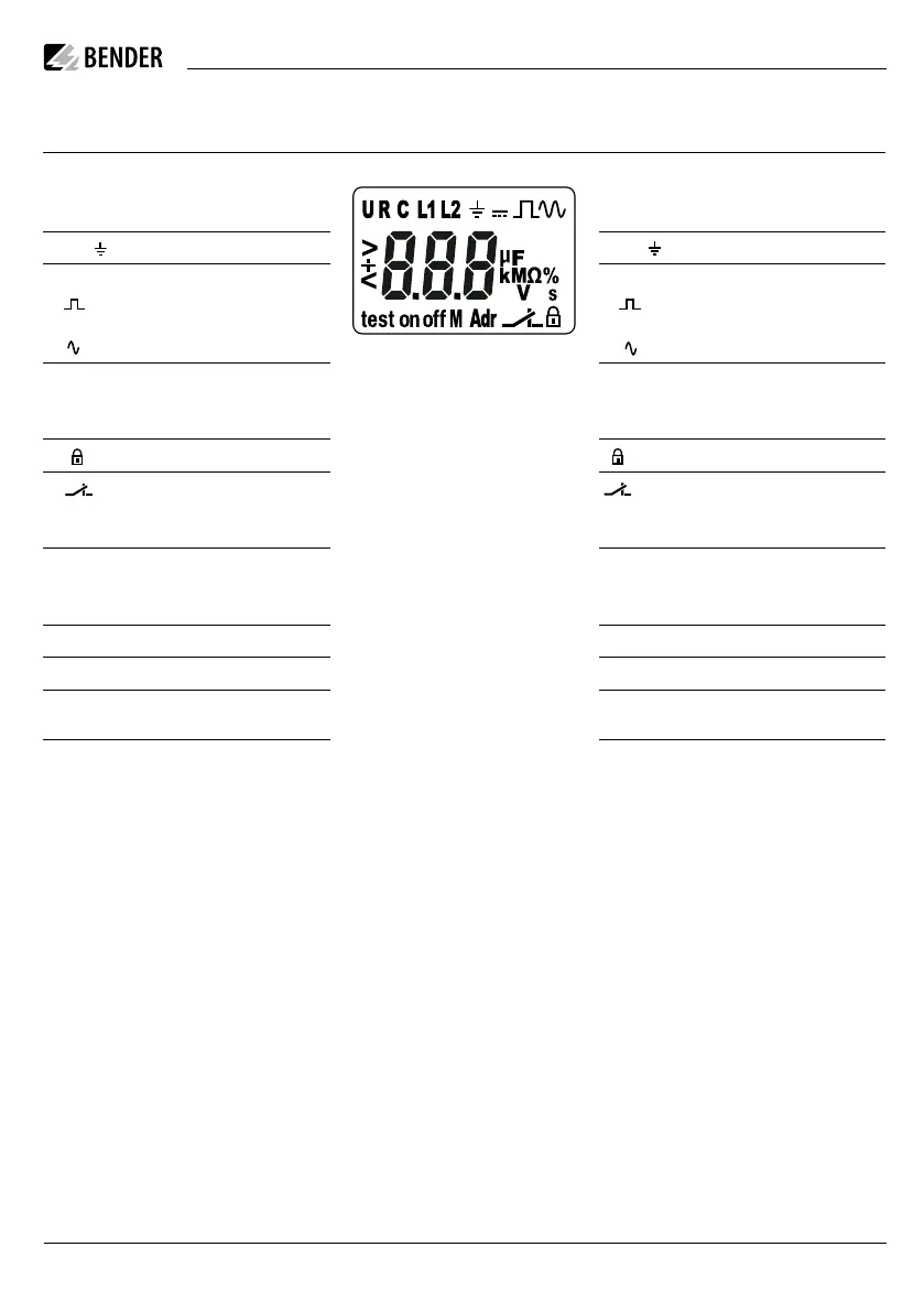
Display-Elemente
Funktion Display Function
U
R
C
Netznennspannung U
n
Isolationswiderstand R
F
Netzableitkapazität C
e
U
R
C
Nominal system voltage U
n
Insulation resistance R
F
System leakage capacitance C
e
L1,L2, Überwachter Leiter L1,L2, Monitored conductor
= Spannungsart DC
Störungsfreie Messwertaktuali-
sierung
Spannungsart AC
= Voltage type DC
Disturbance-free measurement
value update
Voltage type AC
µF
kMΩ%
V s
Einheiten µF
kMΩ%
V s
Measured values and units
Passwortschutz aktiviert Password protection enabled
Im Menübetrieb wird die Arbeits-
weise des jeweiligen Alarmrelais
angezeigt.
In menu mode, the operating
mode of the respective alarm re-
lay is displayed
Adr Kommunikationsschnittstelle mit
Messwert: isoData-Betrieb
Adr Communication interface with
measured value: isoData operati-
on
M Fehlerspeicher aktiviert M The fault memory enabled
on, off Zustandsymbole on, off Condition symbols
test Test aktiv test Test active
<,+,> Kennung für Ansprechwerte und
Ansprechwertverletzung
<,+,> Identification for response values
and response value violation
Technische Daten
()* = Werkseinstellung
Isolationskoordination nach IEC 60664-1/IEC 60664-3
Bemessungsspannung ............................................................ 240 V
Überspannungskategorie ..............................................................III
Versorgungsspannung
Versorgungsspannung U
s
........................................ AC 100…240 V
..................................................................................DC 24…240 V
Toleranz von U
s
.......................................................... -30…+15 %
Frequenzbereich U
s
........................................................ 47…63 Hz
Eigenverbrauch .........................................................≤ 3 W, ≤ 9 VA
Überwachtes IT-System
Netznennspannung U
n
...................................3(N)AC, AC 0…690 V
..................................................................................DC 0…1000 V
Netznennspannung nach UL508 ...........................AC/DC 0…600 V
Toleranz von U
n
..............................................AC +15 %, DC +10 %
Frequenzbereich von U
n
........................................ DC, 15…460 Hz
Display elements
ISOMETER® isoPV425
isoPV425_D00028_04_Q_DEEN/ 11.2022 5

 Loading...


