2 isoRW425_D00052_06_Q_DEEN / 11.2023
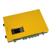
ISOMETER® isoRW425
ISOMETER® isoRW425
Insulation monitoring device
This quick-start guide does not replace the manual!
You can download the manual from our homepage.
Make sure that the relevant personnel has read the
manual and understood all instructions relating to
safety.
https://www.bender.de/en/service-support/download-area/
I
This document contains only an overview of the
most important technical data. The complete
tabular data can be found in the manual.
Quick-start guide for the following devices
Manual
Scope of delivery
• ISOMETER® isoRW425
• Mounting clip
• Quickstart DE/EN
• Safety instructions
Intended use
The ISOMETER® monitors the insulation resistance R
F
(R mode) or the insulation impedance Z
F
(Z mode)
of unearthed AC/DC main circuits (IT systems) with
nominal system voltages of 3(N)AC, AC, AC/DC or
DC 0…440 V. DC components existing in 3(N)AC, AC/DC
systems do not influence the operating characteristics,
when a minimum load current of DC 10 mA flows.
A separate supply voltage U
s
allows deenergised sys-
tems to be monitored as well. The maximum permissi-
ble system leakage capacitance C
e
is 300 μF in R mode
and 1 μF in Z mode.
Any use other than that described in this quickstart is
regarded as improper.
Bestimmungsgemäße Verwendung
Das ISOMETER® überwacht den Isolationswiderstand R
F
(R-Mode) oder die Isolationsimpedanz Z
F
(Z-Mode) von
ungeerdeten AC/DC-Hauptstromkreisen (IT-Systemen)
mit Netznennspannungen von 3(N)AC, AC, AC/DC oder
DC 0…440 V. Die in 3(N)AC, AC/DC-Systemen vorhande-
nen gleichstromgespeisten Komponenten haben kei-
nen Einfluss auf das Ansprechverhalten, wenn mindes-
tens ein Laststrom von DC 10 mA fließt.
Durch die separate Versorgungsspannung U
s
ist auch
die Überwachung eines spannungslosen Systems mög-
lich. Die maximal zulässige Netzableitkapazität C
e
be-
trägt im R-Mode 300 μF und im Z-Mode 1 μF.
Eine andere oder darüber hinausgehende Benutzung
gilt als nicht bestimmungsgemäß.
ISOMETER® isoRW425
Isolationsüberwachungsgerät
Diese Kurzanleitung ersetzt nicht das Handbuch!
Das Handbuch finden Sie auf unserer Homepage zum
Download. Stellen Sie sicher, dass das Personal das
Handbuch und die Sicherheitshinweise gelesen und
verstanden hat.
https://www.bender.de/service-support/downloadbereich/
I
Dieses Dokument enthält nur einen Auszug der
wichtigsten technischen Daten. Die gesamten ta-
bellarischen Daten sind dem Handbuch zu ent-
nehmen.
Kurzanleitung für folgende Geräte
Lieferumfang
• ISOMETER® isoRW425
• Montageclip
• Kurzanleitung DE/EN
• Sicherheitshinweise
Handbuch
Typ/Type Nennspannung/Nominal voltage U
n
Klemme/Terminal Art.-Nr./Art.-No. Handbuch Nr. / Manual No.
isoRW425-D4W-4 AC 100…240 V/DC 24…240 V
Federklemme
Push-wire terminal
B71037000W D00052
isoRW425-D4W-4 AC 100…240 V/DC 24…240 V
Schraubklemme
Screw-type terminal
B91037000W D00052
Montageclip für Schraubmontage (1 Stück je Gerät, Zubehör)
Mounting clip for screw mounting (1 piece per device, accessories)
B98060008 –
 Loading...


