4 isoRW425_D00052_06_Q_DEEN / 11.2023
ISOMETER® isoRW425
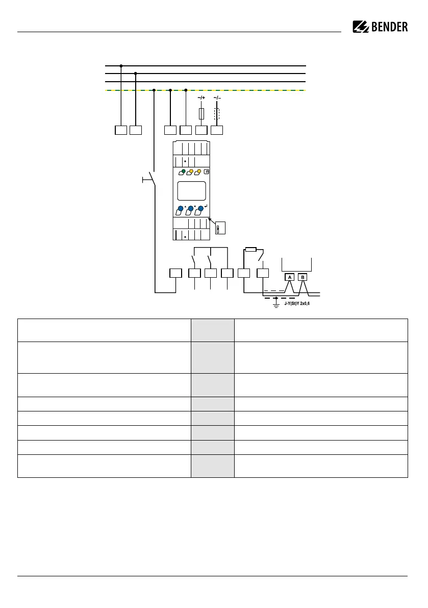
Wiring diagram
i
For UL applications:
Only use 60/75 °C copper lines! For UL and CSA
applications, Feed the supply voltage U
s
via 5 A
back-up fuses.
Anschlussbild
U
S
KE A1 A2
14 24 11
K1 K2
Test / Reset
COM465IP
RS-485
E
6 A6 A
L1/+
L2/-
PE
L3
A
B
R
L2/-
L1/+
T/R
ON
AL1AL2
k
TR
MENU
R
on
o
14
24
11
AT/R B
L1
L2
EKE A2
A1
Anschlüsse
Klemme /
Terminal
Connections
Anschluss an die Versorgungsspannung U
s
über Schmelzsicherung:
Bei Versorgung aus IT-System beide Leitungen absichern. A1, A2
Connection to the supply voltage U
s
via a fuse:
If supplied from an IT system, both lines have to be protected
by a fuse.
Jede Klemme jeweils separat an PE anschließen:
Gleichen Leitungsquerschnitt wie bei „A1“, „A2“ verwenden.
E, KE
Connect each terminal separately to PE:
The same wire cross section as for “A1”, “A2” is to be used.
Anschluss an das zu überwachende IT-Netz L1/+, L2/– Connection to the IT system to be monitored
Anschluss für externe kombinierte Test- und Reset-Taste T/R Connection for the external combined test and reset button
Anschluss Alarmrelais „K1“ 11, 14 Connection to alarm relay “K1”
Anschluss Alarmrelais „K2“ 11, 24 Connection to alarm relay “K2”
RS-485-Kommunikationsschnittstelle mit zuschaltbarem
Terminierungswiderstand
A, B
RS-485 communication interface with selectable
terminating resistance
i
Für UL-Anwendungen:
Nur 60/75-°C-Kupferleitungen verwenden! Die
Versorgungsspannung U
s
bei UL- und CSA-
Applikationen über 5-A-Vorsicherungen zufüh-
ren.
 Loading...


