LINETRAXX® RCM420
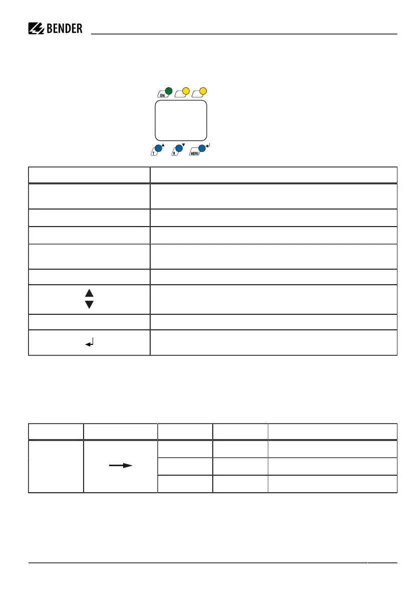
4.2 Function of the operating elements
Operating elementes
Element Function
ON, green
LED ON lighting continuously: Power On
Flashing LED ON: System fault or connection monitoring fault
AL1, yellow
LED AL 1 lights: Response value 1 reached (I
Δn1
)
AL2, yellow
LED AL 2 lights: Response value 2 reached (I
Δn2
)
T
Test button (> 1.5 s): To indicate the available display elements,
to start a self test
R Reset button (> 1.5 s): Deleting the fault memory
Up/Down key (< 1.5 s): Menu items/values
MENU MENU key (> 1.5 s): Starting the menu mode
Enter key (< 1.5 s): Confirm menu item, submenu item and value.
Enter key (> 1.5 s): Back to the next higher menu level.
4.3 Menu structure
All adjustable parameters are listed in the columns ‘menu item’ and ‘adjustable parameters’. A display-like
representation is used to illustrate the parameters in the column menu item. Different alarm categories can
be assigned to the alarm relays K1, K2 via the submenus r1, r2. This is done by activation or deactivation of the
respective function.
Menu Sub menu Menu item Activation Adjustable parameter
>I2 - (HI)
I
Δn2
(alarm2, main alarm )
>I1 - (HI)
I
Δn1
as % of I
Δn2
(alarm 1, prewarning)
AL
(response
values)
Hys -
Hysteresis I
Δn1
/ I
Δn2
RCM420_D00057_06_M_XXEN/12.2023 15
 Loading...