Operation and setting
20
RCMA423_D00063_03_M_XXEN/03.2021
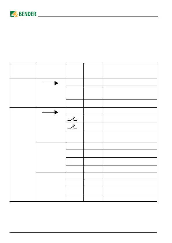
5.3 Menu structure
All adjustable parameters are listed in the columns "menu item" and "adjus-
table parameters". A display-like representation is used to illustrate the para-
meters in the column menu item. Different alarm categories can be assigned
to the alarm relays K1, K2 via the submenus r1, r2. This is done by activation or
deactivation of the respective function.
Menu
Sub
Menu
Menu
item
Activati
on
Adjustable parameter
AL
(response -
values)
> I2 - (Hi)
I
Δn2
(Alarm 2, main alarm)
> I1 - (Hi)
I
Δn1
as % of I
Δn2
(Alarm 1, prewarning)
Hys -
Hysteresis I
Δn1
/ I
Δn2
out
(output
control)
M ON Fault memory (on/off/con)
1
-
Operating mode K1 (n.c.)
2
-
Operating mode K2 (n.c.)
RL -
Reload function (memory =
off)
r1
(K1: (assign-
ment alarm
category)
1 Err ON Device error at K1
r1 I1 ON
Prewarning I
Δn1
at K1
r1 I2 off
Main alarm I
Δn2
at K1
1 tES ON Device test
r2
(K2: (assign-
ment alarm
category)
2 Err ON Device error at K2
r2 I1 off
Prewarning I
Δn1
at K2
r2 I2 ON
Main alarm I
Δn2
at K2
2 tES ON Device test