22
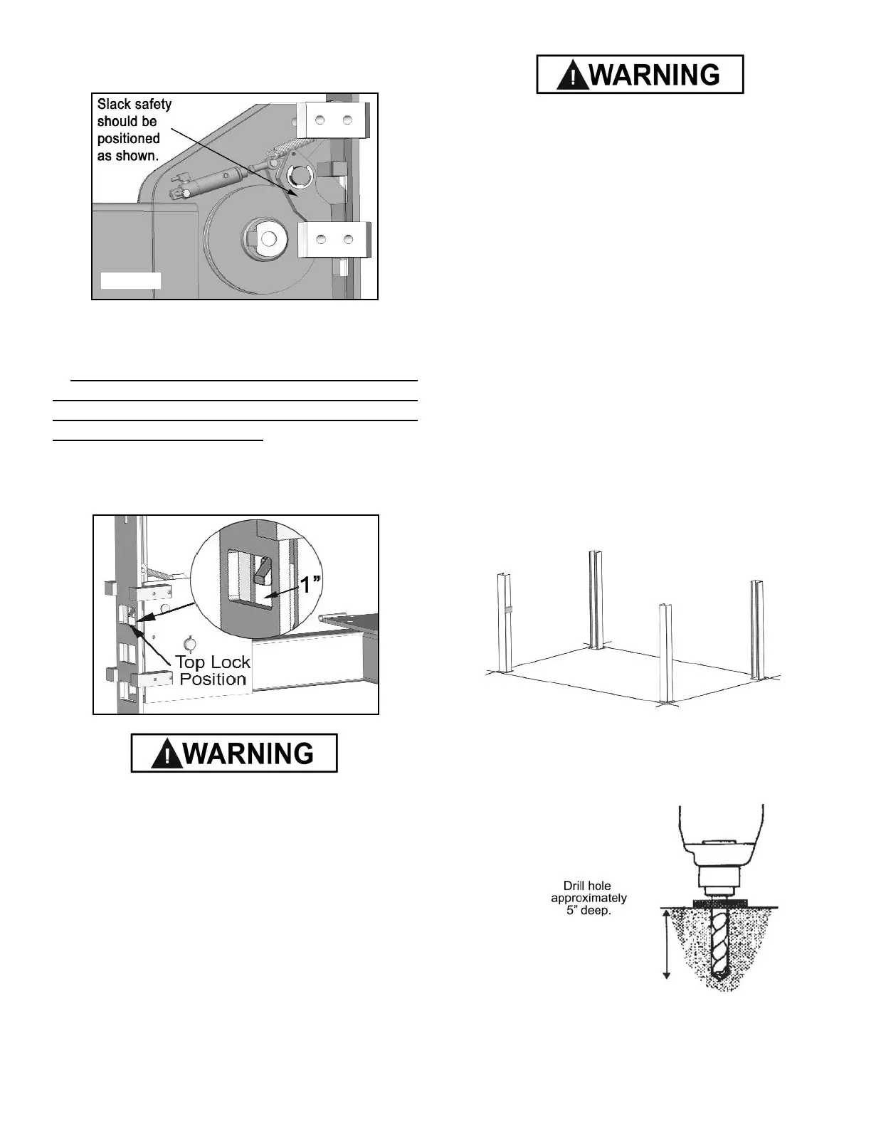
5. Check to make sure that all slack safety locks are cleared
and free. (See Fig. 14.1)
6. Continue pressing the raise button until the cables get
taught and the lift starts to move.
7. RAISE LIFT UNTIL THE CYLINDER BOTTOMS OUT
AND THE LIFT ST
OPS. ADJUST EACH CABLE SO THAT
EACH SAFETY LOCK RESTS AT ONE INCH ABOVE THE
TOP SAFETY LOCK POSITION. It may be necessary to
tighten or loosen each cable to reach the proper height. The
cable nuts MUST be tightened until there is at least one inch
of threads protruding through the nut. (See Fig. 14.2)
All cable nuts MUST be tightened on each end until there
is at least one inch of threads protruding through the nut.
Failure to do so could result in serious injury or death.
NOTE:
There will be initial stretching of the cables in the
beginning and/or with increased loads. Adjust the cables
as outlined above a week after first use, then every
three to six months thereafter depending on usage
and/or to compensate for stretch.
8. After connecting the air supply, press the PUSH BUTTON
AIR VALVE and check that all safety locks are functioning
properly. Lower the lift by pressing the push button air valve
and power unit lowering valve simultaneously.
KEEP HANDS AND FEET CLEAR. Remove hands and feet
from any moving parts. Keep feet clear of lift when lowering.
Avoid pinch points.
9. Check all MAIN SAFETY LOCKS to make sure they
move freely and spring back to the lock position when
released. Lubricate all SAFETY PIVOT points with WD-40
or equal.
10. Run the lift up and down a few times to insure that the
locks are engaging uniformly and that the safety release
mechanisms are functioning. Re-adjust if necessary.
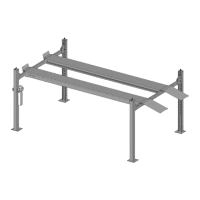
STEP 15
( Anchoring The Columns )
1. Before proceeding, double check the measurements and
make certain that the bases of each column are square and
aligned with the chalk line. Raise the lift up and down and
make sure it operates properly at the locations prescribed by
the markings on the floor. (See Fig. 15.1.)
2. Using the base plate on each column as a guide, drill each
anchor hole approximately 4-1/2” deep using a rotary hammer
drill and 3/4” concrete bit.. ( See Fig. 15.2 )
3. After drilling, remove dust thoroughly from each hole using
compressed air and/or bristle brush. Make certain that the
columns remain aligned with the chalk line.
Fig. 14.1
Fig. 14.2
Fig. 15.1
Fig. 15.2
 Loading...