23
ALWAYS WEAR SAFETY GOGGLES.
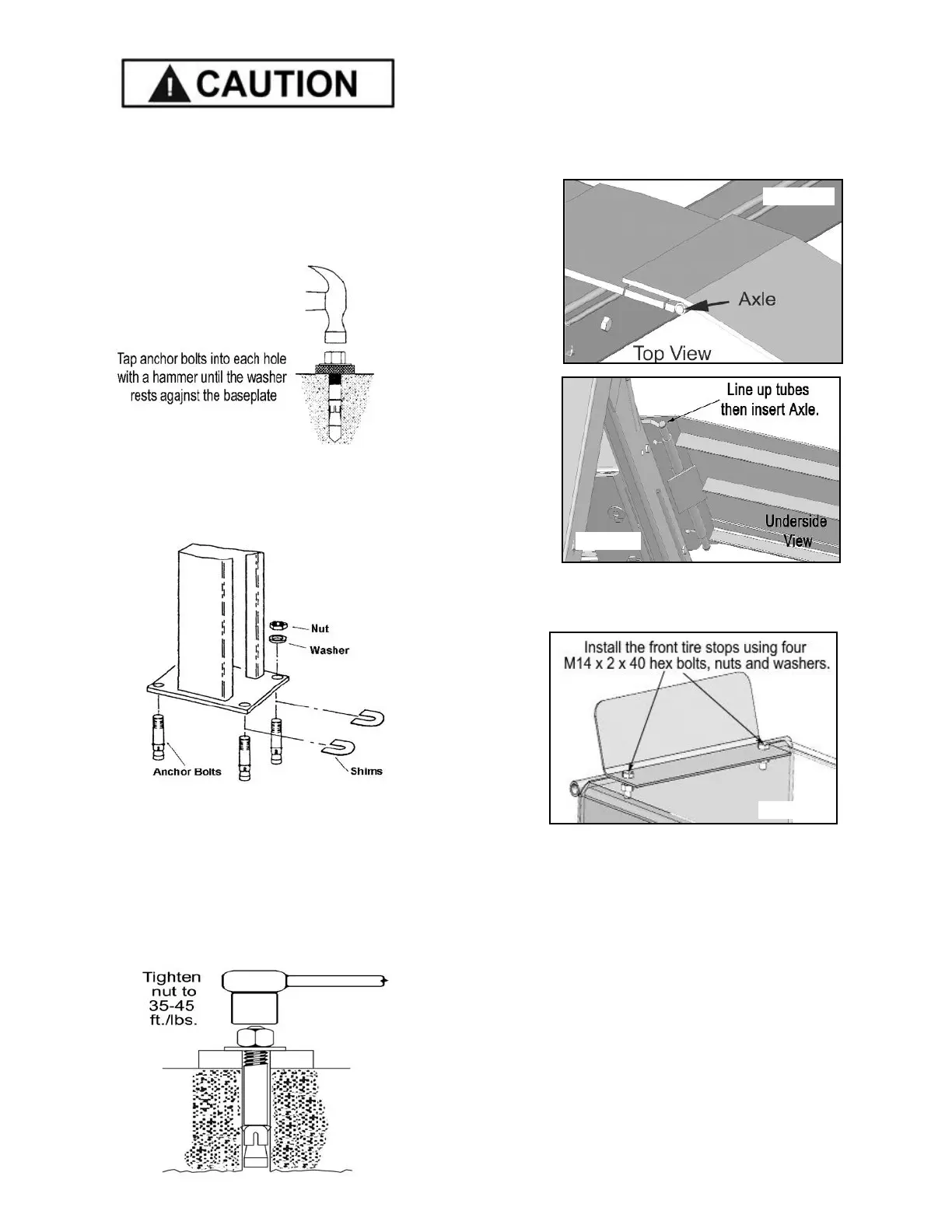
4. Assemble the washers and nuts on the anchors then tap
into each hole with a hammer until the washer rests against
the base plate. Be sure that if shimming is required, enough
threads are left exposed. ( See Fig. 15.3 )
5. If shimming is required, insert the shims as necessary
under the base plate so that when the anchor bolts are tight-
ened, the columns will be plumb. (See Fig. 15.4)
6. After any necessary shims are installed, tighten each
anchor nut to 35-45 ft./lbs. IMPORTANT - If anchor bolts do
not holed when torqued to required amount, concrete must
be replaced. Saw cut and remove 24” x 24” square area
under each column base then repour with reinforced 2500
PSI concrete to a depth of six inches minimum, keying new
concrete under existing floor. (See Fig. 15.5.)
STEP 16
( Attaching Approach Ramps/ Tire Stops )
1. Install the approach ramps on the entry side of the lift.
(See Fig. 16.1 & 16.2 )
2. Install the front tire stops at the forward side of the lift using
the M14 x 2 hex bolts, nuts and washers. ( See Fig. 16.3)
STEP 17
( Leveling / Synchronizing )
1. Using an engineer’s automatic Level (transit), locate
the Level, at a convenient location in the shop that allows
an unobstructed view of all four corners of the runways.
2. Follow the Level manufacturer’s instructions for proper
setup of the Level. Be sure it is adjusted level in all
directions.
3. Raise the lift approximately 30"- 40". Then lower the lift
until all primary safeties are engaged in each column and
the runways are completely resting on the primary
safeties.
Fig. 15.3
Fig. 15.4
Fig. 15.5
Fig. 16.1
Fig. 16.2
Fig. 16.3


 To Next Page