P-9000LT/F Low-Rise Pit Lift 16 P/N 5900022 — Rev. B — Nov. 2019
Create Chalk Line Guides
Make sure to plan out, in advance, where the P-9000LT/F is going to go:
• Clearance. If you are installing the P-9000LT/F over a pit, you are restricted as to where you can
put it. Be sure to make sure there is adequate clearance on all sides.
• Console. The Console must be positioned near the Lift; the Hydraulic Hoses that come with the
P-9000LT/F are optimized for up to 30 inches between the Lift and the Console.
• Operator. The Operator at the Console
must
have a full, unobstructed view of the Lift.
• Power. The Console must also be positioned near an appropriate power source.
• Hydraulic Cylinders on the inside. The two Frames are
not
interchangeable. The Hydraulic
Cylinders must go on the inside (on the pit side if installing over a pit). The holes in the Platforms for
the optional Lift Arms must go on the outside.
• Set up Chalk Line Guides. Create Chalk Line Guides to make sure the Lift gets installed where
you want it to get installed.
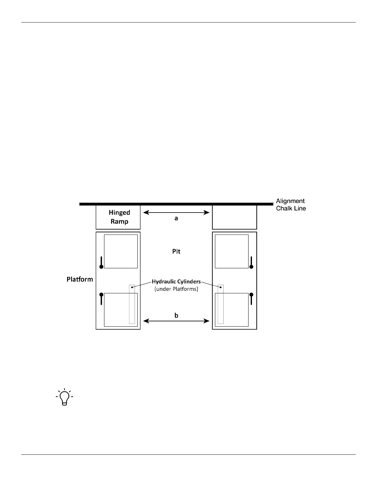
To create Chalk Line Guides:
1. Decide where you want the Lift.
2. Create an Alignment Chalk Line where you want one end of the P-9000LT/F.
Make the Alignment Chalk Line longer than the width of the P-9000LT/F and the Pit.
3. Move the two Frames into position: the Hinged Ramp ends just inside the Alignment Chalk Line
and the inside edges of the Frames aligned with the Pit.
The two Frames are not interchangeable; the Hydraulic Cylinders on the Bases need to be on the
inside, closer to the Pit.
Tip This procedure assumes you are installing the Lift over a pit. If not, create two
additional Chalk Line Guides: they need to be perpendicular to the Alignment Chalk
Line, parallel to each other, and the distance apart you want the two Platforms (in the
range of 36" to 42" / 914 mm to 1,066 mm).