XPR-9 Series Two-Post Lifts
19
P/N 5900371 — Rev. D2 — May 2023
Creating Chalk Line Guides XPR-9TF Only
Create Chalk Line Guides on the ground for the two Posts prior to moving them into position. Use the
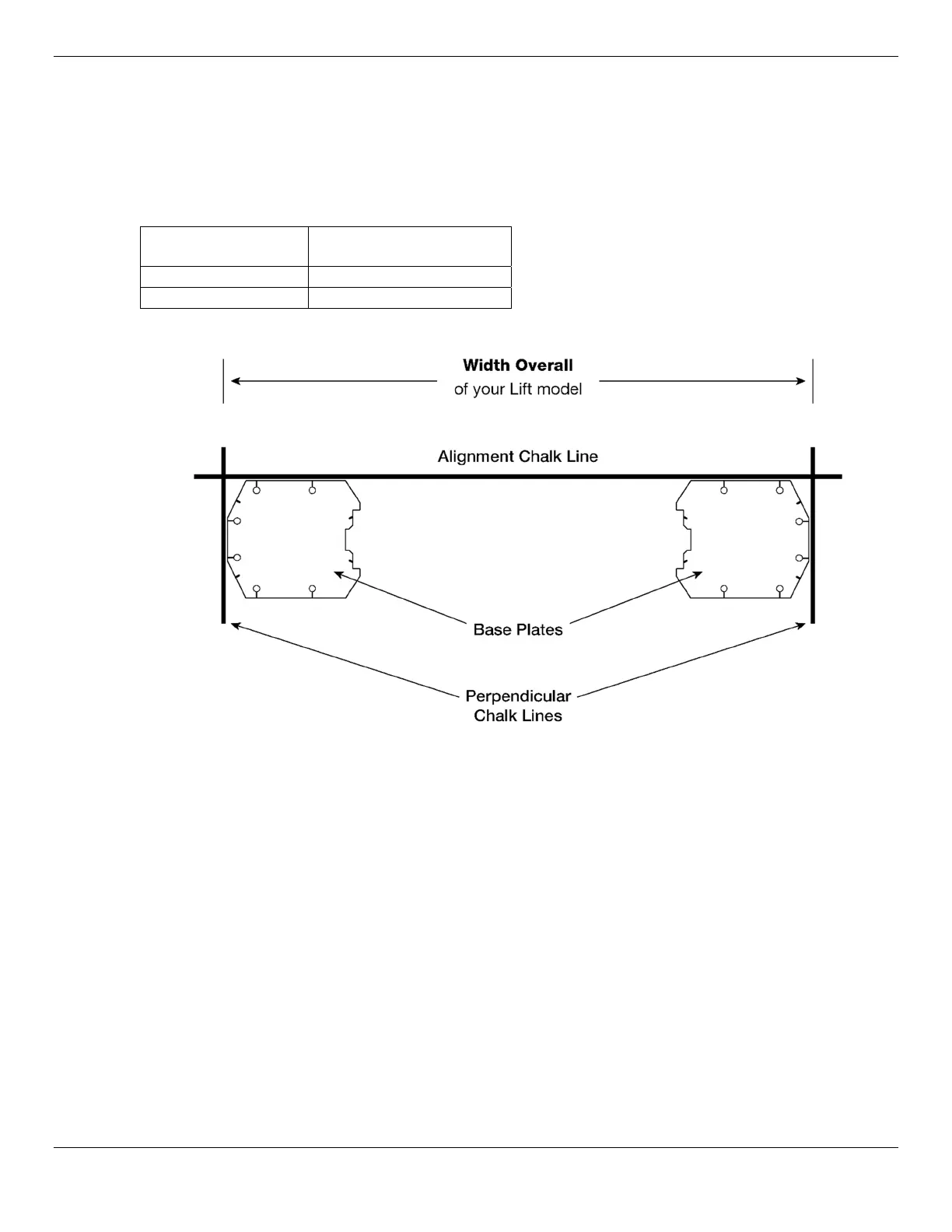
Width Overall value for your Lift model to determine where to place the Chalk Line Guides. The
Width Overall value is defined as the distance from the back of one base plate to the back of the other
base plate. The XPR-9SBT anchoring was created when the concrete recess was formed see pg.
17.
Lift Model Width Overall
XPR-9TF Narrow
132 in. / 3,353 mm
XPR-9TF Wide
145 in. / 3,683 mm
The following drawing shows how to create Chalk Line Guides for your Lift.
Not to scale. Components removed for clarity.
To add the Chalk Line Guides:
1. Decide where you want to locate the Lift.
2. Create an Alignment Chalk Line at the Front of the Lift. For Symmetric Lifts, see the drawing above.
For Asymmetric Lifts, put the Alignment Chalk Line through the notches; see the drawing on the
previous page.
Make the Alignment Chalk Line longer than the Width Overall setting for your Lift model.
Make sure to use the Width Overall setting for Narrow or Wide orientation.
3. Create two Perpendicular Chalk Lines at 90° angles to the Alignment Chalk Lines at the Width
Overall distance for the Lift model you are installing.
The two Perpendicular Chalk Lines must be X distance from each other, where X is the Width
Overall setting (Narrow or Wide, depending on your selection) for your Lift model.
4. Put the Base Plates into the corners created by the Chalk Line Guides, as shown in the drawing on
this page.
 Loading...