12
STEP 4
(Site Layout)
1. Determine which side of the lift will be the approach side.
2. Now determine where the power unit will be located.
The POWER SIDE column has the power unit mounting
bracket attached to the side.
3. Use the chart on this page to determine which lift width
layout you would like to use.
4. Once a location is determined, use a carpenters chalk
line to layout a grid for the post locations. Keep all
dimensions square within 1/8” (3mm) or malfunctioning of
the lift can occur.
5. After the post locations are properly marked, use chalk
or crayon to make an outline of the posts on the oor at each
post location using the post base plates as a template.
(See Fig 4.1)
6. CHECK ALL DIMENSIONS TWICE and make sure that
the layout is perfectly square.
CHALK LINE
FOR XPR-9 CONFIGURATIONS USE BASE PLATE EDGES TO ALIGN POSTS
Fig 4.1
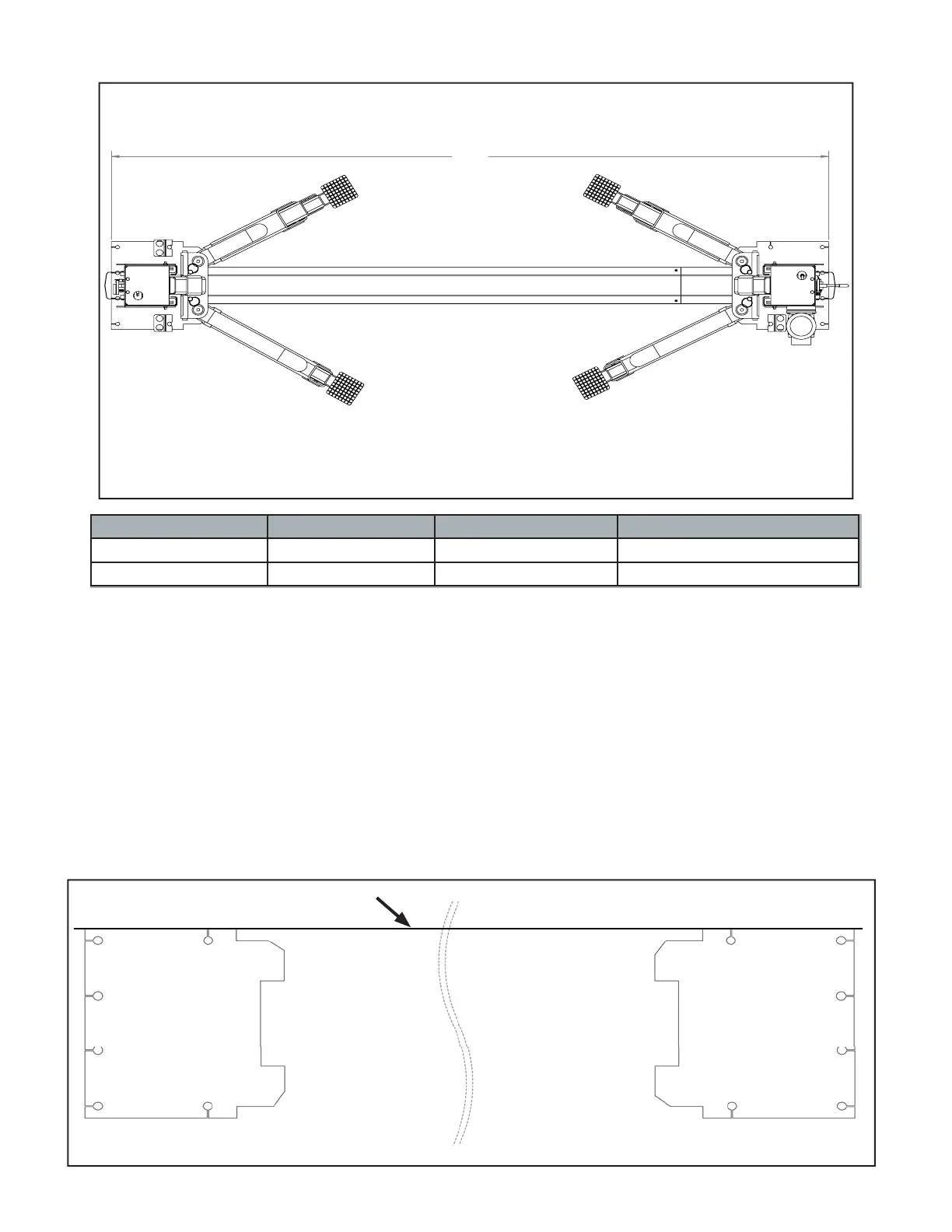
SITE LAYOUT / FLOOR PLAN
A
Model Configuration A Capacity
XPR-9 Narrow 3353 mm / 132” 9,000 LBS
XPR-9 Wide 3683 mm / 145” 9,000 LBS