19
®®
Section 3 - Mounting the Components
SECTION 3 - MOUNTING THE COMPONENTS
Introduction
Please read this section to get an overall view of the steps involved in installing
Control panels from the KYO Unit range.
The end of the stranded conductor must not be soft soldered in places where it is
subject to contact pressure. The Mains wiring must comply with the rules for
double or reinforced insulation. Use an adhesive cable grip to secure the wires
to the terminal boards.
Boxes and Accessories
Metal and Plastic boxes are available.
The Metal Box (BOX-M) kit includes the following parts:
18 Balance Resistors — 10 Kohm
4 plastic PCB supports
1 x 12cm Earth wire (Yellow-Green) with eyelet [13c]
4 hexagonal nuts — M3
2 Parker screws — 2.9 x 7.5 to secure the Frontplate
The Plastic Box (BOX-P) kit includes the following parts:
18 Balance Resistors — 10 Kohm
1 x 40 cm Earth wire (Yellow-Green) without eyelet [13b]
2 Parker screws — 2.9 x 7.5 to secure the PCB
1 Parker screw — 2.9 x 9.5 to secure the BAQ35T12 Switching Power Supply
2 Parker screws — 3.9 x 9.5 to secure the Frontplate
1 Parker screw — 3 x 14.2 to secure the Mains Screw Terminal
2 Parker screws — 3 x 8 to secure the Transformer or BAQ15T12.
The Large Metal Box (BOX-L) kit includes the following parts:
18 Balance Resistors — 10 Kohm
1 x 13 mm plastic support for the PCB
4 plastic supports for the PCB
2 x 12 cm Earth wire (Yellow-Green) with eyelet [13c]
1 hexagonal nut — M3
1 plastic Snatch microswitch bracket [11e]
2 x 3mm cogged metal washers
2 screws 3x6
2 screws 3x8
2 Parker screws — 2.9 x 7.5 to secure the frontplate
1 “Protected Enviroment” label
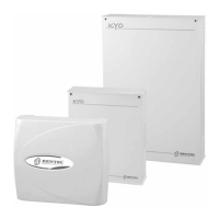
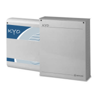
Metal box BOX-M
Plastic box BOX-P
Large Metal Box
BOX-L
 Loading...