27
®®
Section 3 - Mounting the Components
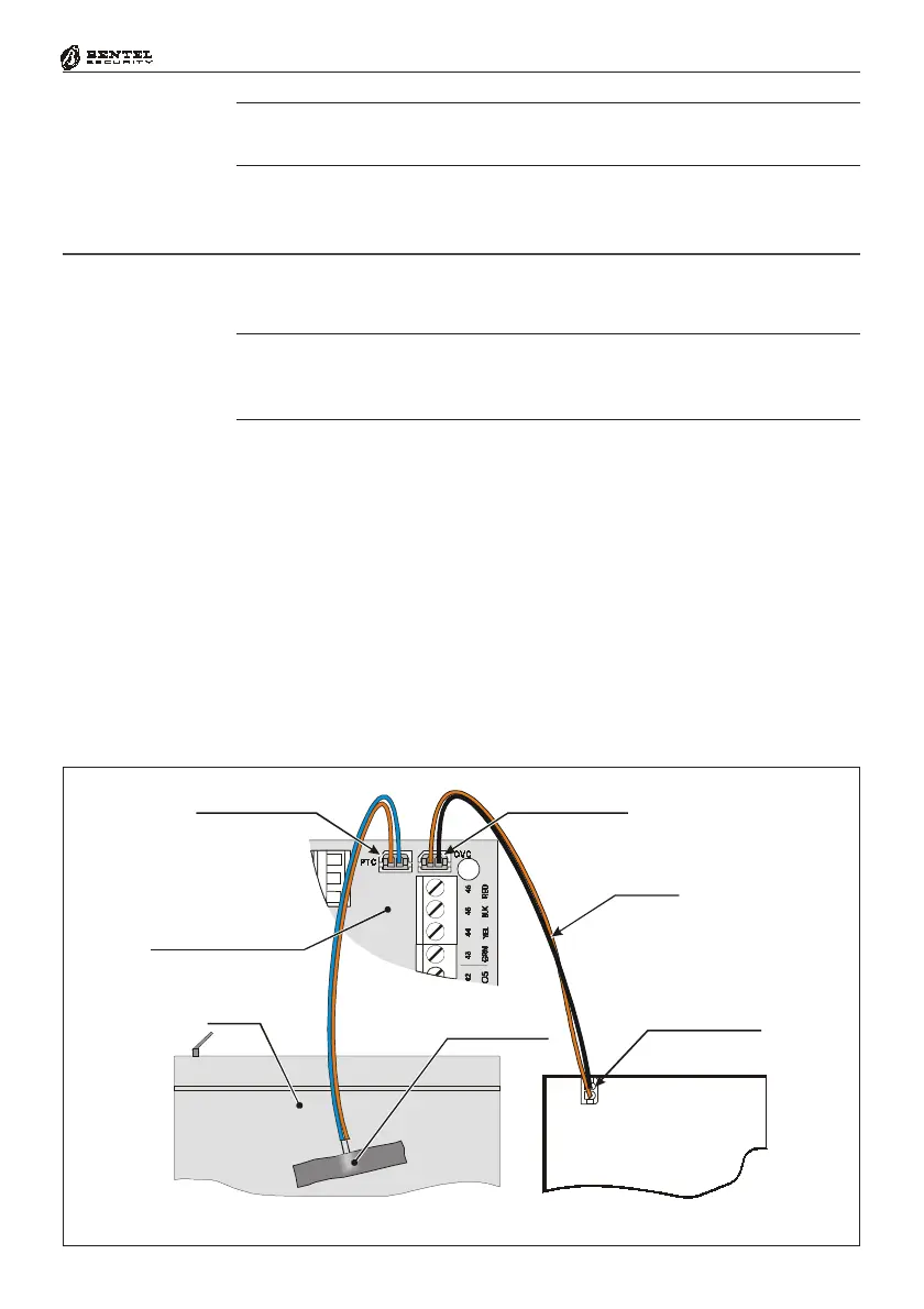
Fig. 3.5 - Connecting the KST Thermal Probe to ‘G’ series PCBs
Switching
Power Supply
(BAQ35T12 or BAQ15T12)
Battery
KYO UNIT
Control Circuit (PCB)
PTC Connector OVC Connector
KST Thermal
Probe
NTC Connector
OVC-Link
To install the NC2/VOX Voice Board, work carefully through the relevant steps
(Metal box or Plastic box), and refer to Fig. 3.6.
NOTE: If you are connecting an NC2/VOX Voice Board to a Control panel
that is already in service, ensure that the Mains and Battery have been DIS-
CONNECTED before starting the connection procedure.
Metal box
1. Remove the paper from the self-adhesive rubber gasket, and position it in
the centre of the 4 board support locations on the backplate.
2. Insert the reverse-locking board supports [3a], then attach the NC2/VOX
(refer to Fig. 3.3). If you are using a BOX-L, locate the boar as shown in Fig.
2.5 or 2.6.
3. Connect the Flat cable to connector A on the NC2/VOX Voice board, and to
Connector B on the PCB.
Plastic box
1. Slot the NC2/VOX board in the holder [12b] — LEDs to the top.
2. Connect the Flat cable to connector A on the NC2/VOX Voice board, and to
Connector B on the PCB.
Connecting the NC2/VOX Voice Board
If you are connecting a KST thermal probe to a Control panel with a BAQ15T12
Power Supply, ensure that the BAQ15T12 on-board Jumper [22b] is inserted.
For further information, refer to the Insert in the KST package.
 Loading...