23
Bentone B40 MF/B45-2 MF
For installers
E1P
Y1
Y2
Y1
Y2
I
N
N
2
1
L
V1
V2
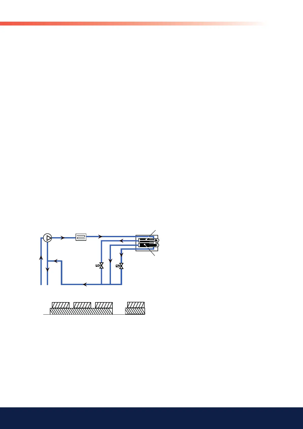
P Oil pump
E1 Preheater
I Nozzle assembly
L Leak pipe
N1 Nozzle 1
N2 Nozzle 2
Y1 Solenoid valve 1 NO
Y2 Solenoid valve 2 NC
V1 Cut valve 1
V2 Cut valve 2
3.2 B45-2 MF 2-stage burner
When the installation calls for heat, the burner's preheater starts to heat the
oil. Once the oil reaches the set temperature, the burner receives the signal
to start. Hot oil is fl ushed throughout the burner's oil system.
After the end of the blow period, the min. load solenoid valve (Y1) receives
voltage and closes. The oil pressure builds up in the nozzle holder and the
cut valve (V1) for min. load opens. The oil is atomised in the nozzle (N1) and
ignited. A small amount of oil and the nozzle assembly compressed air fl ow
is channelled back to the return side of the pump through the leak oil line (L).
Solenoid valve (Y2) for maximum load opens when the installation calls for
maximum load. The pressure difference created over the cut valve (V2) for
maximum load makes this valve open. The oil is atomised in the nozzle and
ignited.
When the heat in the installation reaches break temperature, solenoid valve
(Y2) for maximum load closes to reduce to minimum load. The pressure
equalisation which then takes place over the max. load cut valve (V2) gets
this to close and the fl ame is reduced to min. load.
Once the installation has reached the desired temperature, a solenoid valve
(Y1) is rendered without power and then opened; cut valve (V1) is then
subsequently closed. This process extinguishes the burner fl ame. In the
same process, oil heating is also interrupted.