11.Installation examples
11.1.Example 1: ACM D2/S2 0.37 kW - 2.2 kW (1 x 230V)
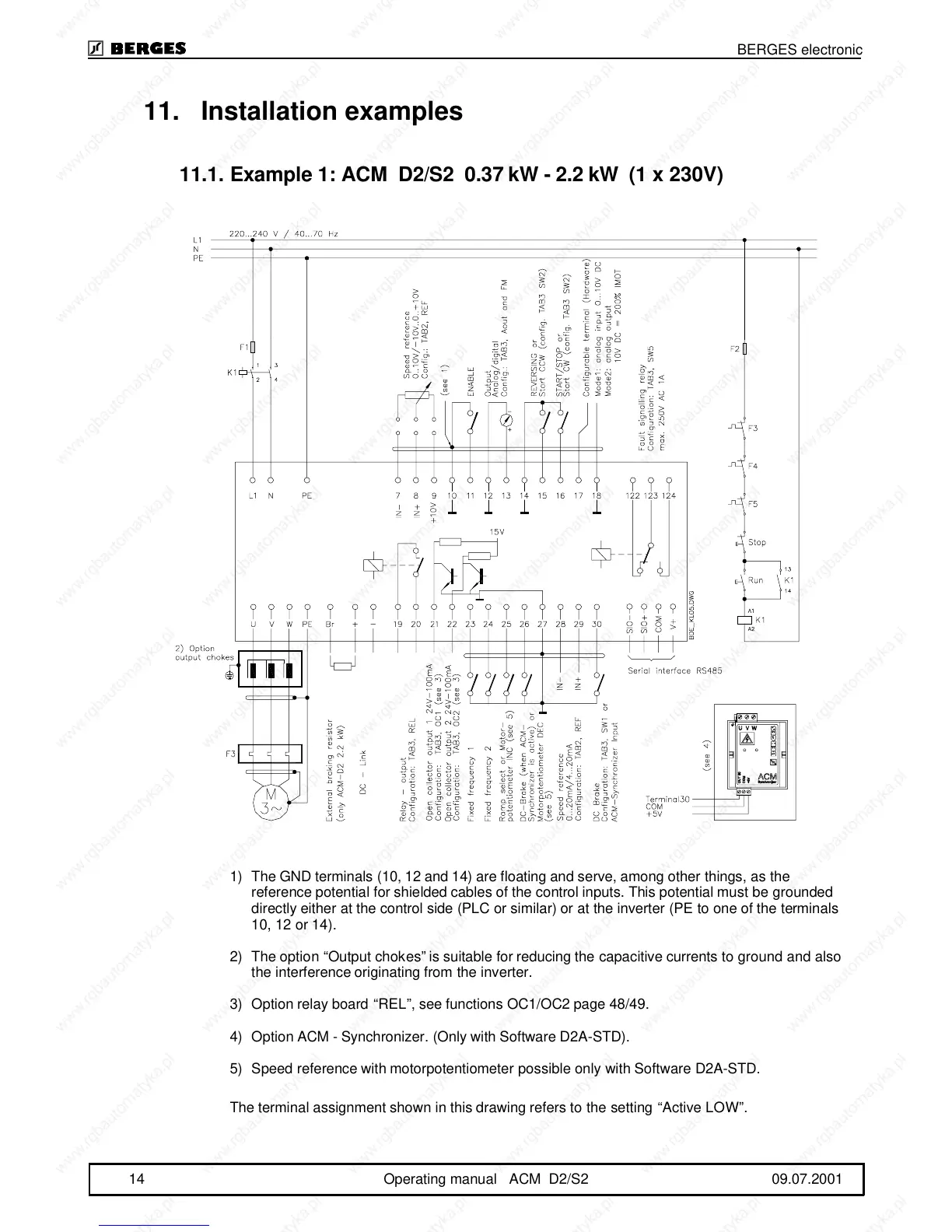
1)The GND terminals (10, 12 and 14) are floating and serve, among other things, as the
reference potential for shielded cables of the control inputs. This potential must be grounded
directly either at the control side (PLC or similar) or at the inverter (PE to one of the terminals
10, 12 or 14).
2)The option “Output chokes” is suitable for reducing the capacitive currents to ground and also
the interference originating from the inverter.
3)Option relay board “REL”, see functions OC1/OC2 page 48/49.
4)Option ACM - Synchronizer. (Only with Software D2A-STD).
5)Speed reference with motorpotentiometer possible only with Software D2A-STD.
The terminal assignment shown in this drawing refers to the setting “Active LOW”.
BERGES electronic
14 Operating manual ACM D2/S2 09.07.2001