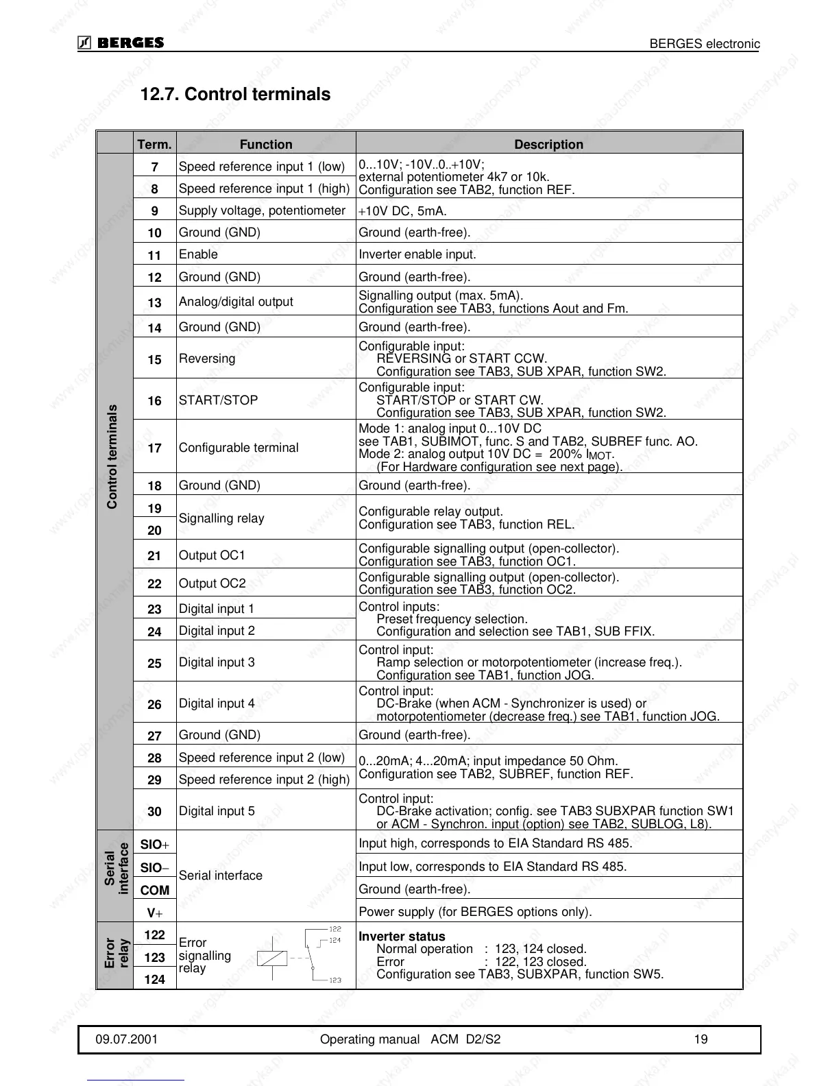
12.7.Control terminals
Term. Function Description
7
Speed reference input 1 (low)
0...10V; -10V..0..+10V;
external potentiometer 4k7 or 10k.
Configuration see TAB2, function REF.
8
Speed reference input 1 (high)
9
Supply voltage, potentiometer
+10V DC, 5mA.
10
Ground (GND) Ground (earth-free).
11
Enable Inverter enable input.
12
Ground (GND) Ground (earth-free).
13
Analog/digital output
Signalling output (max. 5mA).
Configuration see TAB3, functions Aout and Fm.
14
Ground (GND) Ground (earth-free).
15
Reversing
Configurable input:
REVERSING or START CCW.
Configuration see TAB3, SUB XPAR, function SW2.
16
START/STOP
Configurable input:
START/STOP or START CW.
Configuration see TAB3, SUB XPAR, function SW2.
17
Configurable terminal
Mode 1: analog input 0...10V DC
see TAB1, SUBIMOT, func. S and TAB2, SUBREF func. AO.
Mode 2: analog output 10V DC = 200% I
MOT
.
(For Hardware configuration see next page).
18
Ground (GND) Ground (earth-free).
19
Signalling relay
Configurable relay output.
Configuration see TAB3, function REL.
20
21
Output OC1
Configurable signalling output (open-collector).
Configuration see TAB3, function OC1.
22
Output OC2
Configurable signalling output (open-collector).
Configuration see TAB3, function OC2.
23
Digital input 1
Control inputs:
Preset frequency selection.
Configuration and selection see TAB1, SUB FFIX.
24
Digital input 2
25
Digital input 3
Control input:
Ramp selection or motorpotentiometer (increase freq.).
Configuration see TAB1, function JOG.
26
Digital input 4
Control input:
DC-Brake (when ACM - Synchronizer is used) or
motorpotentiometer (decrease freq.) see TAB1, function JOG.
27
Ground (GND) Ground (earth-free).
28
Speed reference input 2 (low)
0...20mA; 4...20mA; input impedance 50 Ohm.
Configuration see TAB2, SUBREF, function REF.
29
Speed reference input 2 (high)
30
Digital input 5
Control input:
DC-Brake activation; config. see TAB3 SUBXPAR function SW1
or ACM - Synchron. input (option) see TAB2, SUBLOG, L8).
SIO
+
Serial interface
Input high, corresponds to EIA Standard RS 485.
SIO
−
Input low, corresponds to EIA Standard RS 485.
COM
Ground (earth-free).
V
+
Power supply (for BERGES options only).
122
Error
signalling
relay
Inverter status
Normal operation: 123, 124 closed.
Error : 122, 123 closed.
Configuration see TAB3, SUBXPAR, function SW5.
123
124
Control terminals
Serial
interface
Error
relay
BERGES electronic
09.07.2001 Operating manual ACM D2/S2 19