1) Inverter stopped. Automatic error reset as soon as the link voltage rises above the
undervoltage value.
2) Inverter stopped. If the AUTORESET function is activated (see TAB3, SUB XPAR, function
SW3), a reset is possible by setting or the
START/STOP
input, or the
ENABLE
input, or by
setting the setpoint to zero.
3) The motor is decelerated with the deceleration ramp and the inverter is stopped. An error
reset can be performed as described in Item 2.
4) The motor is decelerated with the deceleration ramp and the inverter is stopped until the
temperature doesn’t fall below the limit value. If the AUTORESET function is activated
(see TAB3, SUB XPAR, function SW3), a reset is possible by setting or the
START/STOP
input, or the
ENABLE
input, or by setting the setpoint to zero.
5) Behaviour with Softw. D2A-STD: see 4)
Behaviour with Softw. D2A-1300: see 2)
14.8. Hardware error messages
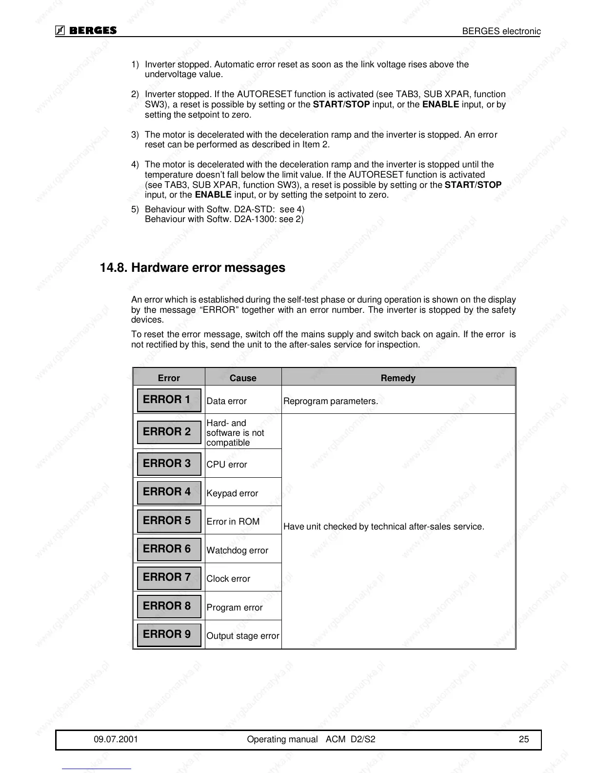
An error which is established during the self-test phase or during operation is shown on the display
by the message “ERROR” together with an error number. The inverter is stopped by the safety
devices.
To reset the error message, switch off the mains supply and switch back on again. If the error is
not rectified by this, send the unit to the after-sales service for inspection.
Error Cause Remedy
Data error Reprogram parameters.
Hard- and
software is not
compatible
Have unit checked by technical after-sales service.
CPU error
Keypad error
Error in ROM
Watchdog error
Clock error
Program error
Output stage error
ERROR 1
ERROR 2
ERROR 3
ERROR 4
ERROR 5
ERROR 6
ERROR 7
ERROR 8
ERROR 9
BERGES electronic
09.07.2001 Operating manual ACM D2/S2 25