18. Faults and remedies
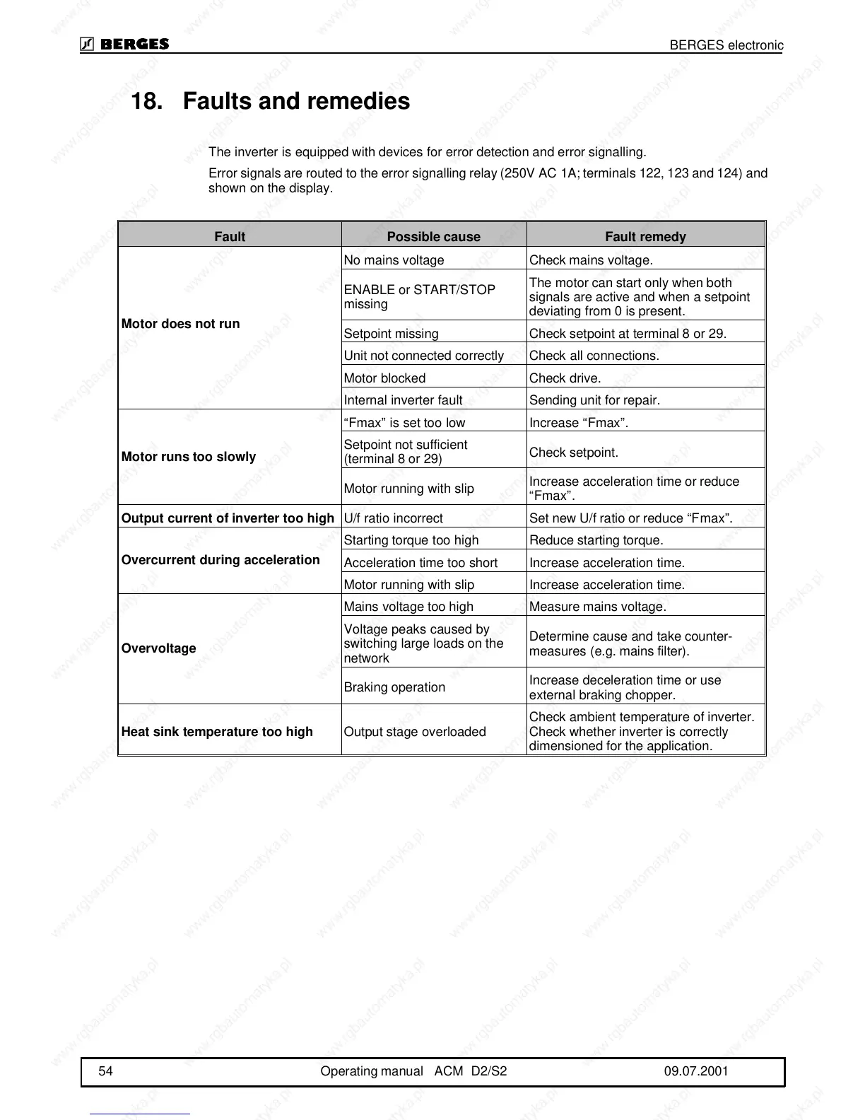
The inverter is equipped with devices for error detection and error signalling.
Error signals are routed to the error signalling relay (250V AC 1A; terminals 122, 123 and 124) and
shown on the display.
Fault Possible cause Fault remedy
Motor does not run
No mains voltage Check mains voltage.
ENABLE or START/STOP
missing
The motor can start only when both
signals are active and when a setpoint
deviating from 0 is present.
Setpoint missing Check setpoint at terminal 8 or 29.
Unit not connected correctly Check all connections.
Motor blocked Check drive.
Internal inverter fault Sending unit for repair.
Motor runs too slowly
“Fmax” is set too low Increase “Fmax”.
Setpoint not sufficient
(terminal 8 or 29)
Check setpoint.
Motor running with slip
Increase acceleration time or reduce
“Fmax”.
Output current of inverter too high
U/f ratio incorrect Set new U/f ratio or reduce “Fmax”.
Overcurrent during acceleration
Starting torque too high Reduce starting torque.
Acceleration time too short Increase acceleration time.
Motor running with slip Increase acceleration time.
Overvoltage
Mains voltage too high Measure mains voltage.
Voltage peaks caused by
switching large loads on the
network
Determine cause and take counter-
measures (e.g. mains filter).
Braking operation
Increase deceleration time or use
external braking chopper.
Heat sink temperature too high
Output stage overloaded
Check ambient temperature of inverter.
Check whether inverter is correctly
dimensioned for the application.
BERGES electronic
54 Operating manual ACM D2/S2 09.07.2001