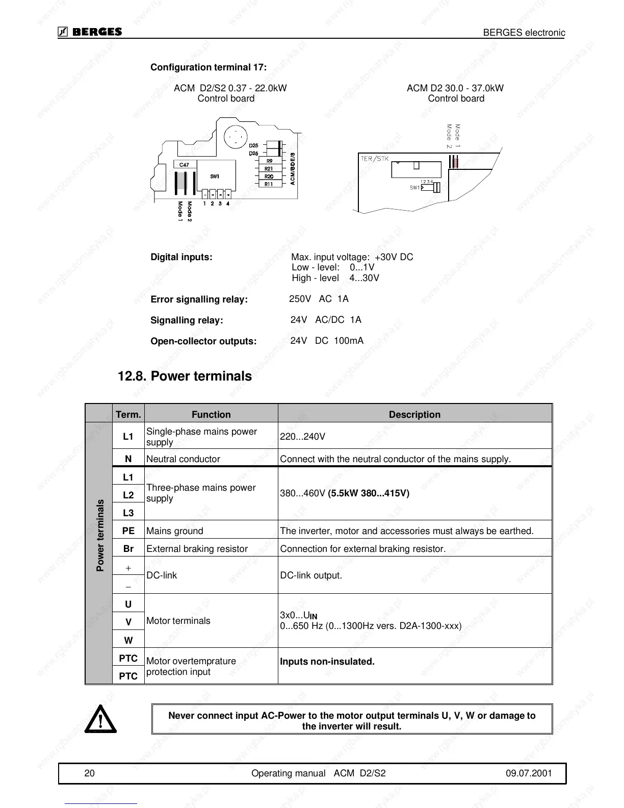
Configuration terminal 17:
ACM D2/S2 0.37 - 22.0kW ACM D2 30.0 - 37.0kW
Control board Control board
Digital inputs:
Max. input voltage: +30V DC
Low - level: 0...1V
High - level 4...30V
Error signalling relay:
250V AC 1A
Signalling relay:
24V AC/DC 1A
Open-collector outputs:
24V DC 100mA
12.8.Power terminals
Term. Function Description
L1
Single-phase mains power
supply
220...240V
N
Neutral conductor Connect with the neutral conductor of the mains supply.
L1
Three-phase mains power
supply
380...460V
(5.5kW 380...415V)
L2
L3
PE
Mains ground The inverter, motor and accessories must always be earthed.
Br
External braking resistor Connection for external braking resistor.
+
DC-link DC-link output.
−
U
Motor terminals
3x0...U
IN
0...650 Hz (0...1300Hz vers. D2A-1300-xxx)
V
W
PTC
Motor overtemprature
protection input
Inputs non-insulated.
PTC
Never connect input AC-Power to the motor output terminals U, V, W or damage to
the inverter will result.
Power terminals
BERGES electronic
20 Operating manual ACM D2/S2 09.07.2001