Dynamic braking protection
TAB2
The dynamic braking circuit can be protected from overload activating this protection
function. If the braking power exceeds the programmed limit, the motor is ramped
down to zero and the inverter is stopped. The programmed value corresponds to the
max. braking power.
0: Braking protection function disabled.
1...15: A value different from 0 corresponds to the braking power limit.
Select the limit value according to the power capability of the
braking circuit.
Range: 0...15
Default: 0
Function MOD: Modulation degree
TAB2
This parameter defines the output voltage the inverter will deliver to the motor when re-
aching the knee-frequency. The diagram shows how the output voltage corresponds to
the Modulation degree.
The maximum output voltage depends from the full line input voltage.
Range: 0...255
Default:
ACM230V 230
ACM400V 245
Function FFB: BOOST form factor
TAB2
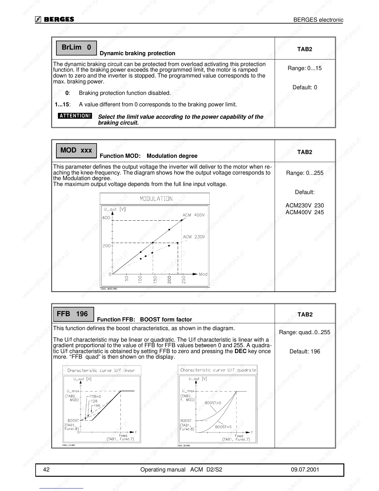
This function defines the boost characteristics, as shown in the diagram.
The U/f characteristic may be linear or quadratic. The U/f characteristic is linear with a
gradient proportional to the value of FFB for FFB values between 0 and 255. A quadra-
tic U/f characteristic is obtained by setting FFB to zero and pressing the DEC key once
more. “FFB quad” is then shown on the display.
Range: quad..0..255
Default: 196
BrLim 0
ATTENTION!
MOD xxx
FFB 196
BERGES electronic
42 Operating manual ACM D2/S2 09.07.2001