This document describes BERMAD Meters Electromagnetic Flowmeters, specifically focusing on various sensor models and their installation, operation, and maintenance.
Function Description
Electromagnetic flowmeters are designed to measure the flow rate of electrically conductive liquids (such as drinking water, wastewater, beverages, fertilizers, and chemical products) with an electrical conductivity of at least 5µS/cm. These flowmeters offer fast response times, high measurement accuracy, and do not obstruct liquid flow, thus causing no pressure drop. They also require minimal maintenance due to the absence of moving parts.
The sensor, a core component, works by inducing an electromotive force (e) in a conductive fluid moving at speed (v) within a magnetic induction field (B). This force is proportional to the speed of the liquid, expressed by the formula: e = kBDv, where B is the constant magnetic field, D is the distance between electrodes (equivalent to the flowmeter diameter), v is the liquid speed, and k is the calibration constant.
The sensors are capable of bidirectional reading, meaning they can measure flow in both directions. By convention, flow in the direction of the arrow (entering in – and exiting in +) is positive, while flow in the opposite direction (entering in + and exiting in -) is negative.
To function, the sensor must be combined with a converter, which processes the electrical signals. Converters are designed with flexible and hybrid electronics to meet modern water management system needs, offering various electrical power solutions.
Important Technical Specifications
The product identification plate provides crucial information for each sensor, including:
- MODEL: Sensor model (e.g., MUT2200EL)
- S/N: Sensor identification number
- DN: Nominal diameter (in inches or mm)
- PN: Nominal pressure (in inches or mm)
- TEMP.: Maximum liquid temperature for process completion
- IP: International degree of protection (e.g., IP68)
- ELECTRODES: Material composition of electrodes (e.g., HC)
- LINING: Lining material (e.g., EBANITE)
- KA: Calibration coefficient
- CE: Marking
Available Sensor Versions:
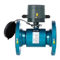
- Flanged sensors: MUT2200EL (Full Bore) and MUT2300 (Reduced Bore).
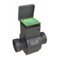
- Wafer sensors: MUT1000EL (Wafer) and MUT1100J (Wafer in plastic material).
- Insertion sensors: MUT1222, MUT2660, and MUT2770.
Operating Temperatures:
For normal and efficient operation, the room temperature must be between -25°C and +60°C (-13°F and +140°F).
- Coating in EBONITE: Min -40°C, Max +80°C (Min -40°F, Max +176°F)
- Coating in PTFE (remote): Min -40°C, Max +130°C (Min -40°F, Max +266°F)
- Coating in PTFE (compact): Min -40°C, Max +80°C (Min -40°F, Max +176°F)
- Coating in PTFE (separate high temperature): Min -40°C, Max +180°C (Min -40°F, Max +356°F)
- MUT1100J: Min 0°C, Max +80°C (Min 32°F, Max +176°F)
- INSERZIONI: Min -20°C, Max +80°C (Min -4°F, Max +176°F)
Maximum Tightening Torque [Nm] for Flanged and Wafer Sensors:
The manual provides a detailed table for various DN, PN, and BULLONI (bolt) configurations, specifying tightening torques for PTFE, Ebanite, and OR NBR linings across MUT2200EL, MUT1000EL, and MUT110J models. For instance, a DN50, PN40, 4xM16 bolt sensor with PTFE lining requires 55 Nm, and with Ebanite, 30 Nm.
Insertion Meters (MUT1222, MUT2660, MUT2770):
- MUT1222: Available in three sizes (S-Small, M-Medium, L-Large) for pipes from DN50 to DN2600. It features Hot-Tap functionality, allowing assembly/disassembly under pressure, and a 1/8" GAS pressure tap. Insertion depth calculation is I = Di/8.
- MUT2660: Suitable for fixed installation in pipes from DN80 up to DN500. Requires a 40mm hole drilling and threaded sleeve welding. Does not have Hot-Tap functionality, so the pipe must be empty for installation/disassembly. Maximum pressure is 10 bar. Insertion depth calculation is I = Di/8.
- MUT2770: Suitable for medium-large diameter pipes, from DN100 up to DN2500. Requires a 50mm hole drilling and flanged sleeve welding. Does not have Hot-Tap functionality, so the pipe must be empty for installation/disassembly. Maximum pressure is 25 bar. Insertion depth calculation is I = Di/8.
Electrical Connection:
- Grounding Cable: Minimum section 2.5 mm² (recommended: 4 mm²), grounding screws M5. Recommended ground resistance value is ≤ 5Ω.
- Separation Cables: Optional single-shielded electrode cables (C022) with PVC outer jacket and shield, and optional double-shielded electrode cables (C028) with PUR outer jacket and external shield, plus additional shielding for measuring electrodes.
Usage Features
Installation Conditions:
- Liquid Conductivity: The liquid must be conductive.
- Pipe Fullness: The pipe must always be full and free from air and bubbles to ensure accurate measurements.
- Input/Output Distances: Specific input and output distances must be maintained as recommended.
- Grounding: Proper grounding instructions must be followed.
- Positioning: The flowmeter must be installed below the piezometric level line connecting the two fluid levels. Avoid placing it above this line.
- U-shaped Tube: For partially filled pipes or downward flow with free exit, the flowmeter should be placed in a U-shaped tube.
- Vertical/Sloped Pipe: Installation on a vertical/sloped pipe with an upward flow direction is recommended to minimize wear and deposits. Avoid vertical pipes with free exit.
- Vibrations: Do not expose the flowmeter to vibrations; install anti-vibration protection if necessary.
- Magnetic Fields: Avoid strong or nearby magnetic fields.
- Negative Pressure: Avoid vacuum conditions in the pipe, as this can damage the coating and displace electrodes.
- Direct Sunlight: Protect the flowmeter from direct sunlight.
- Pipe Alignment: Maximum allowable deviation of pipe flange faces is 0.5 mm. Do not force pipes closer by overtightening bolts.
- Sensor Support: The pipe must support the flowmeter; the sensor should not be used as a pipe support.
- Underground Installations: Remote sensors (IP68/NEMA 6P) can be positioned underground. Use gravel (at least 300mm) around the sensor for drainage and to prevent dirt solidification. Use electrical cable identification tape above the gravel. The sensor cable should pass through a plastic conduit.
- Air Pockets: To avoid air pockets, install flowmeters on pipes with an increasing slope (minimum 1:500) or vertically with an upward flow. Use properly designed and sized air vent valves to release trapped air, especially when pumps start.
- Diameter Reduction: Follow specific guidelines for diameter reduction, including recommended maximum vertex angles (15°) and upstream/downstream straight pipe lengths (e.g., 5DN upstream, 3DN downstream for full bore sensors). Be aware that diameter reduction can cause pressure drop and cavitation, especially with reduced section meters.
- Cathodic Protection: If the pipeline has cathodic protection, isolate the flowmeter by installing isolation bushings and washers on flange bolts, and connect a wire between pipes. Use grounding rings on both ends.
Insertion Meter Specifics:
- Probe Installation: The probe must be installed at 1/8 of the internal diameter of the pipe, which corresponds to the point of average axial speed. The meter axis must intercept the pipe axis.
- Electrode Alignment: The electrodes must be positioned perpendicularly to the flow direction. Incorrect alignment can lead to measurement errors.
- MUT1222 Hot-Tap: This model allows assembly and disassembly with the pipe under pressure. However, for pressures above 5 bar, extreme caution is advised, and for pressures above 10 bar, reducing line pressure is recommended. It includes a safety chain to prevent rapid rod exit.
Maintenance Features
General Maintenance:
- Bolts Tightening: Periodically check the tightness of all fixing nuts. If necessary, ensure correct tightening according to the torque values provided in the manual.
- Grounding Check: Periodically check the earth connections, the integrity of cables, and terminals, and remove any oxidation from contacts.
Cleaning of Ebonite Coatings:
- Cleaning and degreasing organic coatings is a delicate matter. Avoid any acid solution containing HF (hydrofluoric acid) in any concentration.
- The basic solution, such as NaOH, can be used, but only at room temperature. Normal soap is recommended for removing grease and oil.
- If cleaning with soap is not sufficient, washing with a solvent can be carried out. Use products that evaporate rapidly, such as acetone. In this case, dirt must be removed with a cloth moistened with acetone. This operation must be done quickly to avoid aggression on the Ebonite, and immediately afterward, the surface must be dried with a blow of air to allow the solvent evaporation.
Troubleshooting:
Refer to the instruction manual of the converter associated with the specific sensor for troubleshooting problems, causes, and solutions.
Certifications and Technical Features:
Refer to the sensor and converter catalogs to see the list of certifications and all the technical features related to your product.
Sending the Flowmeter to the Manufacturer:
The device is manufactured with extreme care and undergoes rigorous tests before shipment. If installation and maintenance are carried out correctly, it is unlikely that malfunctions will occur. However, if it is necessary to send the device to the manufacturer for any checks or repairs, pay attention to the following points:
- Adhere to legal provisions on environmental protection and securing the health and safety of personnel. The manufacturer can only test and repair those devices returned that have been in contact with products that are risk-free for personnel and environment.
- The manufacturer can perform service on the device only if it is accompanied by the "repair request form" stating that the device can be safely handled.
Product Disposal:
Disposal of the device no longer in use is the responsibility of the user, who must comply with specific laws enforced in the country of installation regarding environmental protection.
- The manufacturer declares that the design, development, and construction of the converter have been carried out in compliance with the directive on the reduction of the use of dangerous substances with particular attention to waste electrical and electronic equipment (WEEE) supporting, from an environmental point of view and the protection of the health of the worker, the intervention of the subjects who participate in the installation, use, and disposal of their products (manufacturers, distributors, consumers, operators involved in WEEE treatment).
- The crossed-out wheelie bin symbol (Fig. 92) contained on the equipment indicates that the product must be collected separately from other waste at the end of its useful life.
- The user must give the equipment at the end of its life to the appropriate waste collection centers for waste electrical and electronic equipment, or return it to the retailer when purchasing a new equivalent type of equipment on a one-for-one basis.
- Appropriate sorted waste collection for the next start-up of the disused equipment for recycling, treatment, and environmentally compatible disposal contributes to avoiding possible negative effects on the environment and favors the reuse and/or recycling of the materials of construction. Unauthorized disposal of the product by the user results in the application of the administrative sanctions provided for by applicable law.