Irrigation IOM
Sensors
| 7 |
1
.
3
PRELIMINARY NOTES
Main parts of the electromagnetic flowmeter are:
Sensor – installed in the tube with the use of flanges and other joints
Converter – can be installed on the sensor (in compact version) or remotely (in remote version) connected
with two pipes
Electromagnetic flowmeters have many important advantages compared to their mechanical counterparts, such
as exceptional long-term stability, maximum process reliability, and zero maintenance. As a result, these sensors
can provide accurate and reliable long-term measurements.
See the following paragraphs for more detailed information on correct installation.
NOTES:
Electromagnetic flowmeters are designed specifically to operate under the following basic
conditions:
1. The liquid must be conductive;
2. Pipe must be always full and free from air and bubbles;
3. The input and output distances must be on recommended settings
4. The grounding instructions must be followed
1
.
4
PRODUCT IDENTIFICATION
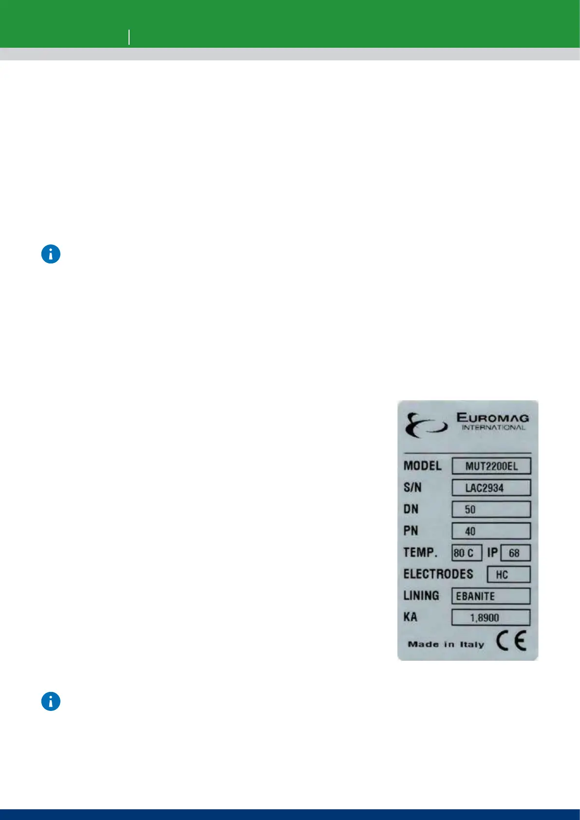
Each Sensor manufactured by EUROMAG INTERNATIONAL has an identification plate (Fig. 1) that displays the
following information::
IDENTIFICATION PLATE
MODEL: Sensor model
S/N: Sensor identification number
DN: Nominal diameter [inches or mm]
PN: Nominal diameter [inches or mm]
TEMP.: Maximum liquid temperature for process completion
IP: International degree of protection
ELECTRODES: Electrodes material composition
LINING: Lining material
KA: Calibration coecient
CE: Marking
The identification plate must never be removed, damaged, or changed. It must also be kept clean from any dirt
deposits, as the data contained are the only safe and unambiguous way to recognize the type of converter and
be able to complete the repair request form attached to this manual.
Fig. 1 Identification plate