MANUAL INSTALLATION
Version: 6.1 (05-12-2011) 27
Outputs on the unit O1-O1 and O2-O2
The unit has an interface for two output signals: These can be
used, f
or instance, for controlling the central heating or
cooling system or for status messages to a building
management system.
Caution:
c The outputs are potential-free contacts (relays). Their
maximum load is 24 V / 1 A.
Options and operation
Options and operation depend on the inputs or output as well
as
on the control panel settings. These are further described
in section Operation.
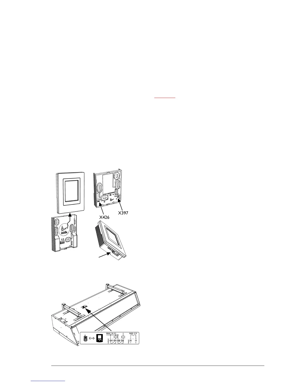
2.8.3 Mounting and connecting control panel
1. Lay the control cable.
2. If t
he external-control input in the control panel is used: lay the
necessary cabling. The cable core diameter is not to
exceed 0.75 mm.
3. Push the operating panel out of the wall holder.
4. Connect the control cable to
terminal X397 and (if
installed) the cable for the external control to terminal
X426 of the wall holder.
5. Screw the wall holder onto the plug socket or the wall.
6. Place the control panel back in the wall holder.
7. Optional: Lock the control panel with the screw on the
underside
.
2.8.4 Connecting control panel to unit
The control panel connections G and D are located on the
connector plate on the upper side of the unit. The two
sockets are identical. One of the two sockets has a dummy
plug.
1. Connect the control cable to the free terminal
G or D.