INSTALLATION COMFORT AIR CURTAIN
34
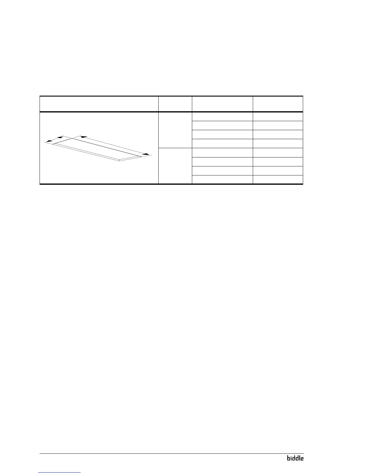
7. Make a hole in the false ceiling with the dimensions stated
in Table 2-6.
2.10 Switching on and checking function
For models connected to a Daikin system CA
2
V and
CA
2
Q:
• Switch on the Daikin indoor units and outdoor unit.
For all models
1. Check the following connections:
-Power supply;
- Control cables between control panel and unit (or
un
its);
-For CA
2
V and CA
2
Q: Control cables between unit(s)
and Daikin components.
- External control components (if used).
2. Switch the power supply on and/or plug in all connected
un
its.
When you switch on the power supply for the first time,
the contr
ol panel searches for connected units and then
immediately displays the number of connected units.
3. During the first start, the installation guide is started.
F
ollow this through to carry out the most frequently
needed settings.
If the installation guide is not displayed, it can be started
wi
th
Menu>Maintenance>Installation.
Table 2-6 Un
it hole dimensions
R
EFEREN
CE
TYPE DIMENSIONS
b
a
a CA
2
S-C 829 mm
CA
2
M-C 829 mm
CA
2
L-C 1113 mm
CA
2
XL-C 1113 mm
b CA
2
100-C 1008 mm
CA
2
150-C 1508 mm
CA
2
200-C 2008 mm
CA
2
250-C 2508 mm