SERVICE COMFORT AIR CURTAIN
64
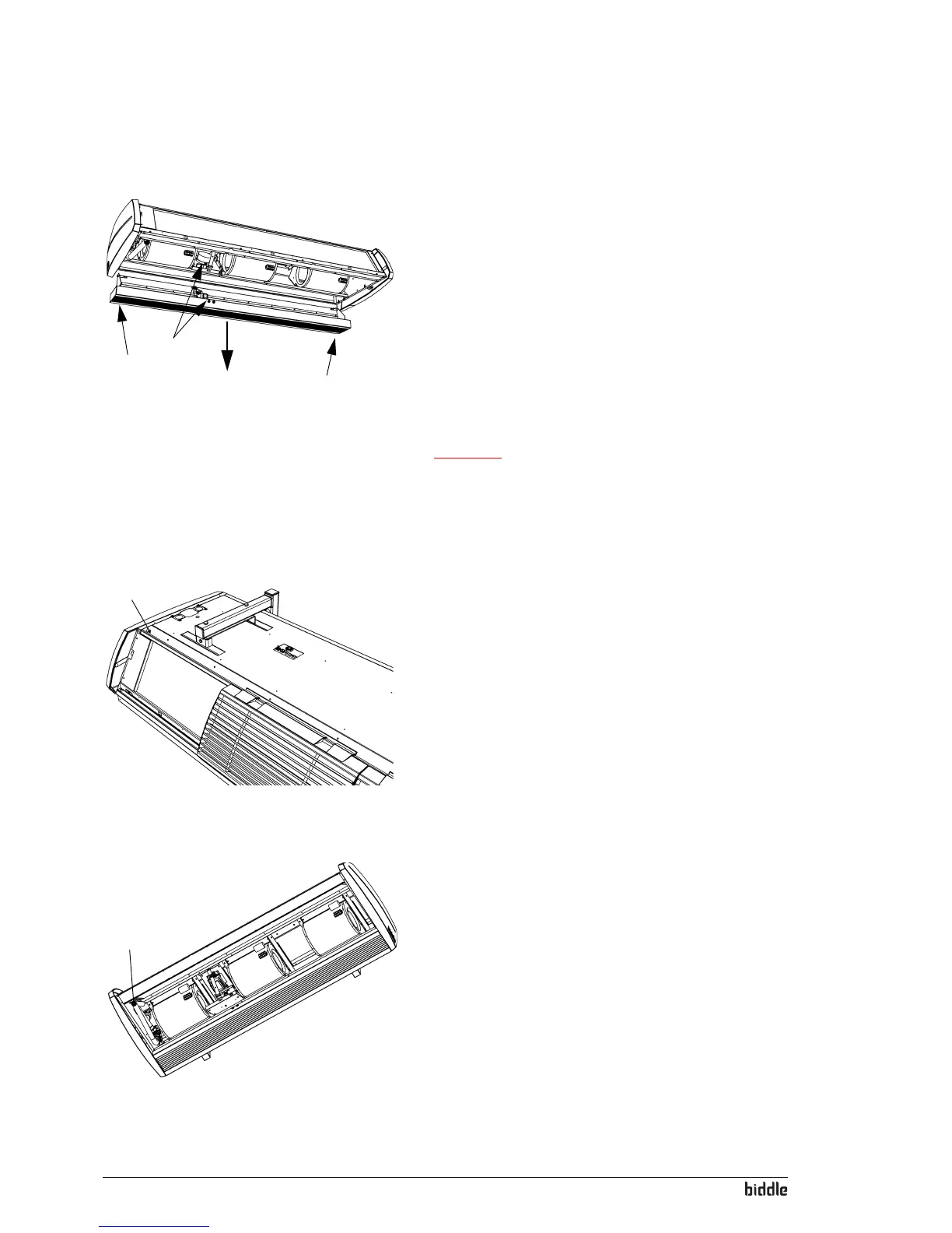
For all models
1
2
2
1. Remove the inspection panel (see section 6.2).
2. The discharge section has the f
ollowing connections to the
electronics module (at 1):
- The valve drive connections on the printed circuit
boa
rd (connectors X140 and X210);
- The earth connection.
Disconnect these connections.
3. Between the fins of the discharge grille
, there are 4 screws
(at 2): Loosen these.
Caution:
c Support the discharge section while loosening the screws.
4. The discharge section is now detached: Remove it carefully.
6.7 Venting the heat exchanger
1
For water-heated models only
The air relief valve 1 is located in the upper left of the unit.
6.8 Bleeding the heat exchanger
1
For water-heated models only
The drain plug 1 is located on the left of the unit.