MANUAL INSTALLATION
Version: 6.1 (05-12-2011) 29
Note:
n Leave about 30 cm excess cable length: it will be needed to
take the electronics out when servicing the unit.
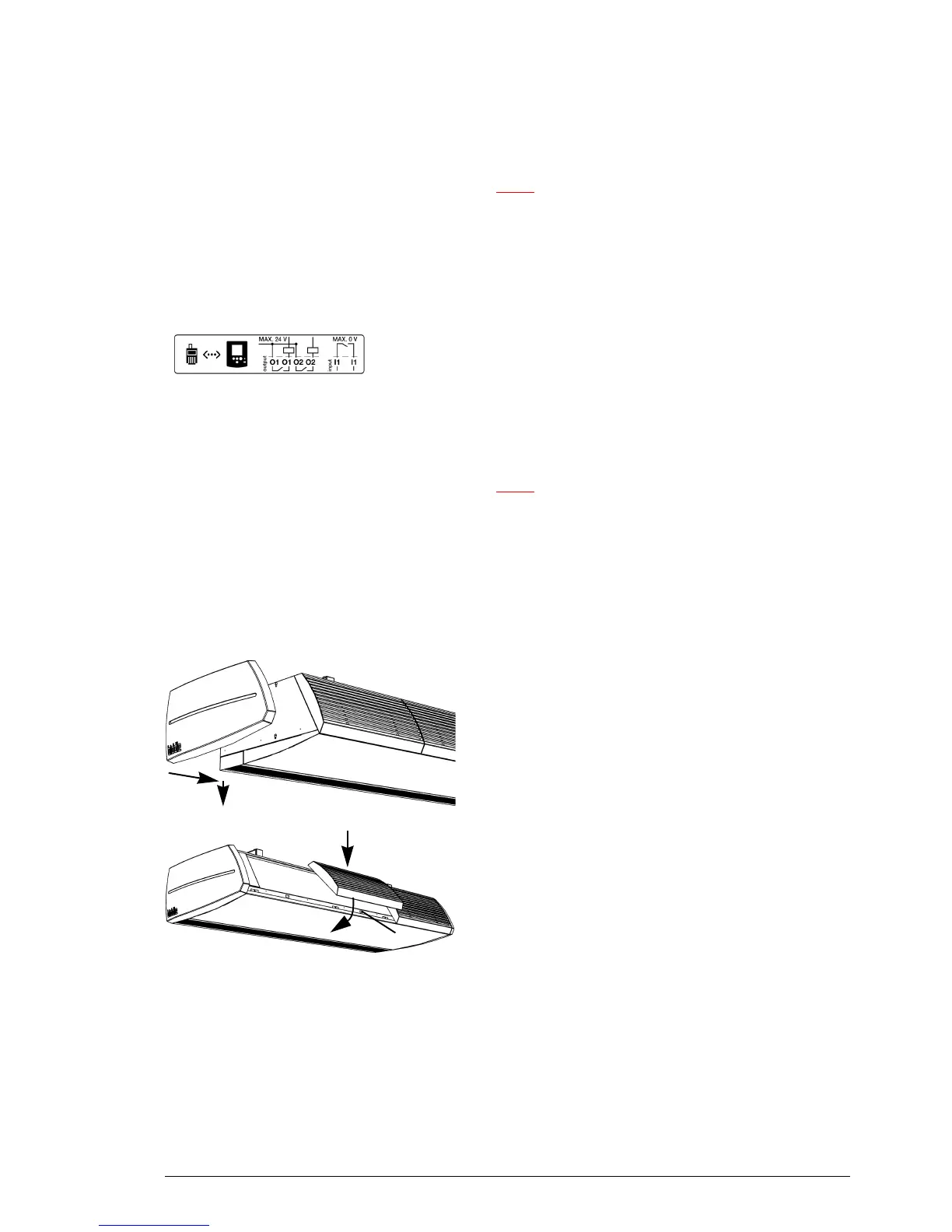
2.8.6 Connecting external controls to the unit
(optional)
The terminals are located in the connector plate on the top of
the unit. The corresponding connectors are located in the
terminals.
• Connect the cable for the output signals to terminal O1-
O1 o
r O2-O2.
• Connect the cable for the input signal to terminal I1-I1.
Note:
n Leave about 30 cm excess cable length: it will be needed to
take the electronics out when servicing the unit.
2.9 Finishing the unit
2.9.1 Finishing free-hanging models
1
2
Position the side caps
1. Fit the end caps to either side of the unit:
- Hook the end caps 1 into the slots in side 2.
- Push the caps down until you hear a click.
If linking two or more units to each other, fit the end caps
to
the outer ends.
3
Position the inlet grilles
2. Fit the inlet grilles to the unit:
- Hook the grilles onto the upper side of the unit.
- The back of each grille has a projection. Fit the grille
w
ith the projection into the rectangular hole 3.