MANUAL INSTALLATION
Version: 6.1 (05-12-2011) 25
6. Put back and screw down the inspection panel.
Warning:
w Always attach the inspection panel using flanged
bolts with milled edges: these are needed for the
earth connection.
7. Connect the power supply cable to the isolation switch.
Caution:
c Do not yet switch the power supply on.
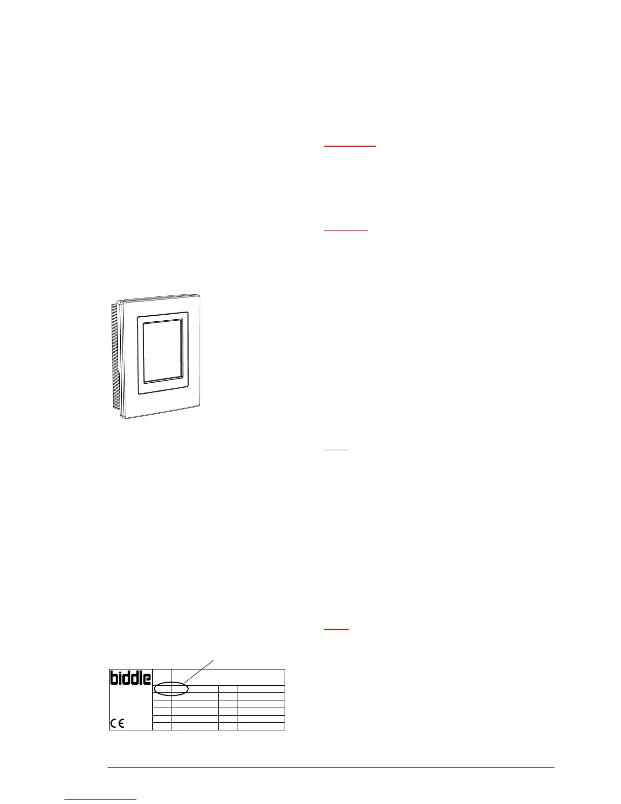
2.8 Installing control panel and external controls
2.8.1 Control panel details
Positioning
• You may fix the control panel either to the wall or to a
sta
ndard socket.
Cabling
Note:
n Take the following into account, otherwise faults may
occur:
- The control cable between the control panel and the
(f
irst) connected unit must not be more than 50 m
long.
- Keep control cables away from electromagnetic fields
and interf
erence sources such as high-voltage cables
and fluorescent-light starters.
- Stretch control cables out or roll them up neatly.
- Do not remove the dummy plug, unless otherwise
stated.
Note:
n Use only control cables from Biddle. Standard modular
telephone cable is not suitable.
Multiple units operated from one control panel
Type CA M-150-W-F
Code 1213 U 230 V 1N~ 50 Hz
Biddle bv
Markowei 4
NL-9288 HA Kootstertille
Nº 5426/1-1 00-01 I
max
L1 2.4 A
I
max
L2 -
M 60 kg I
max
L3 -
Medium LPHW P
motor
0.56 kW
p
max
1400 kPa P
heating
-
code
• Up to 10 units can be connected to one single control
panel. To do so, the units must be interlinked.