HR MANUAL INSTALLATION
Manual version 4.1 (26-07-2018)
en-15
en
n The threaded rods must be secured, otherwise the
unit may fall down.
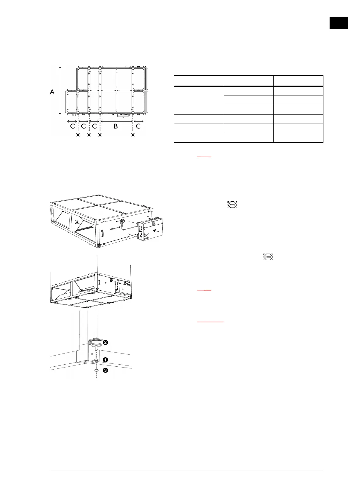
Hanging the unit up
1. Mount the electronics module on the side of the
heat
exchanger module
.
2. Move the heat exchanger module into position.
3. Attach the module to the threaded rods with nuts 1.
n Make sure the rubbers and rings 2 for damping stay
in the right place.
c Make sure that the module is hanging level in both
directions.
With type HR 45, the heat exchanger can sag
slightly. After all the modules are linked, this will be
minimalised.
4. To each threaded rod, apply a lock nut 3.
SIZE TYPE DIMENSIONS
A HR 25 1558 mm
HR 35 2158 mm
HR 45 2758 mm
B all models 1450 mm
C all models 450 mm
x all models 54 mm