INSTALLATION HEAT RECOVERY UNIT
en-22
en
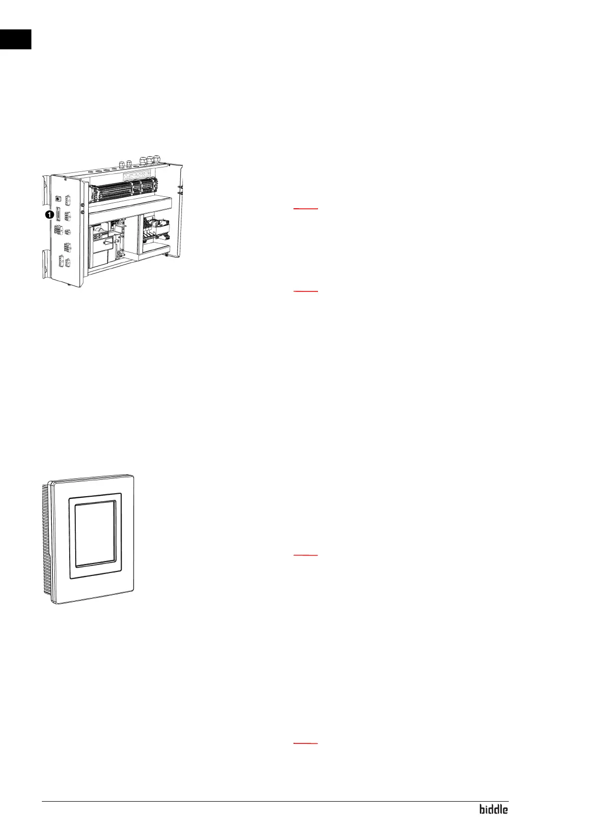
2.7.3 Connecting the unit to Modbus
1. Lay a cable between the Modbus system and the unit.
2. Connect the cable to the electronics module 1, in accord-
ance with the wiring diagram.
n For a more reliable signal, it is possible to connect a
120 Ohm resistor. For this purpose, place a bridge
between positions 1 and B of terminal 52X3 on the
control circuit board in the unit.
n The b-touch control panel is no longer necessary for
the operation. After going through the installation
guide, it can be removed. However, make sure to
keep it to be able to adjust the settings in a later
stage.
2.8 Installing the b-touch control panel (accessory)
2.8.1 Special points regarding the control panel
Positioning
• You can attach the control panel to the electronics mod-
ule, to the wall or to a standard junction box.
Cabling
n Take the following into account, otherwise errors
may occur:
- The length of the control cable between the contro
l
p
anel and the unit connected may not exceed 50 m.
- Keep control cables away from electromagnetic fi
elds
an
d interference sources such as high-voltage ca
bles
an
d fluorescent light starters.
- Lay control cables out straight or roll them in a bifi-
lar coil by folding cables in half before rolling them.
As a result, the magnetic fields will cancel each othe
r
out
to an important extent.
n Use Biddle control cables only. Standard modular
t
elephone cable is NOT suitable.