HR MANUAL INSTALLATION
Manual version 4.1 (26-07-2018)
en-19
en
2. Connect the drive to the valve in accordance with the wir-
ing diagram.
3. Connect the drive to the building management system
or
another contr
ol system.
2.4.2 Connecting the unit
1. Connect the unit to the central heating system.
2. Vent the heat exchangers.
3. Check the connections for leakage.
2.5 Installing condensate drain
The cooling of the air can cause condensation. The unit is fit-
ted with a drain tray(s) to catch condensation water.
1. Connect one of the connection points 1 (15 mm) of the
heat exchanger to a drainage system.
c On models that are used for cooling, also connect
the connection point of the cooling module 2 (15
mm
) to
a drainage system.
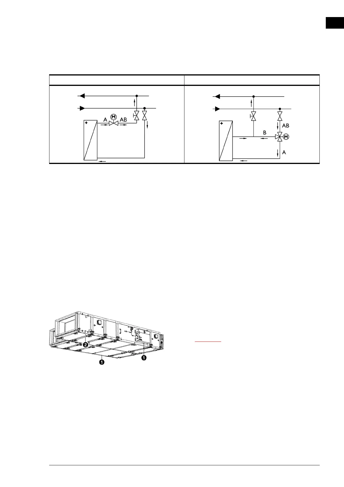
WIRING DIAGRAM 2-WAY VALVE WIRING DIAGRAM 3-WAY VALVE