INSTALLATION HEAT RECOVERY UNIT
en-26
en
Unit output
The unit has an output signal interface (X3). A warning lamp
for dirty filters can be connected to this.
c Keep the cable length to a maximum of 3 metres.
2.11.2 Installing smoke detector or fire alarm (acces-
sory)
In emergencies, the unit can emit an alarm signal or even
actively deal with the problem by functioning in a special
mode. (See menu > Configuration > 60. Function of inputs)
This function can be activated by the building management sys-
tem (register address 435) or by an external sensor.
If an external sensor is used:
1. Place a smoke detector or fire alarm (not supplied) at
a
su
itable location.
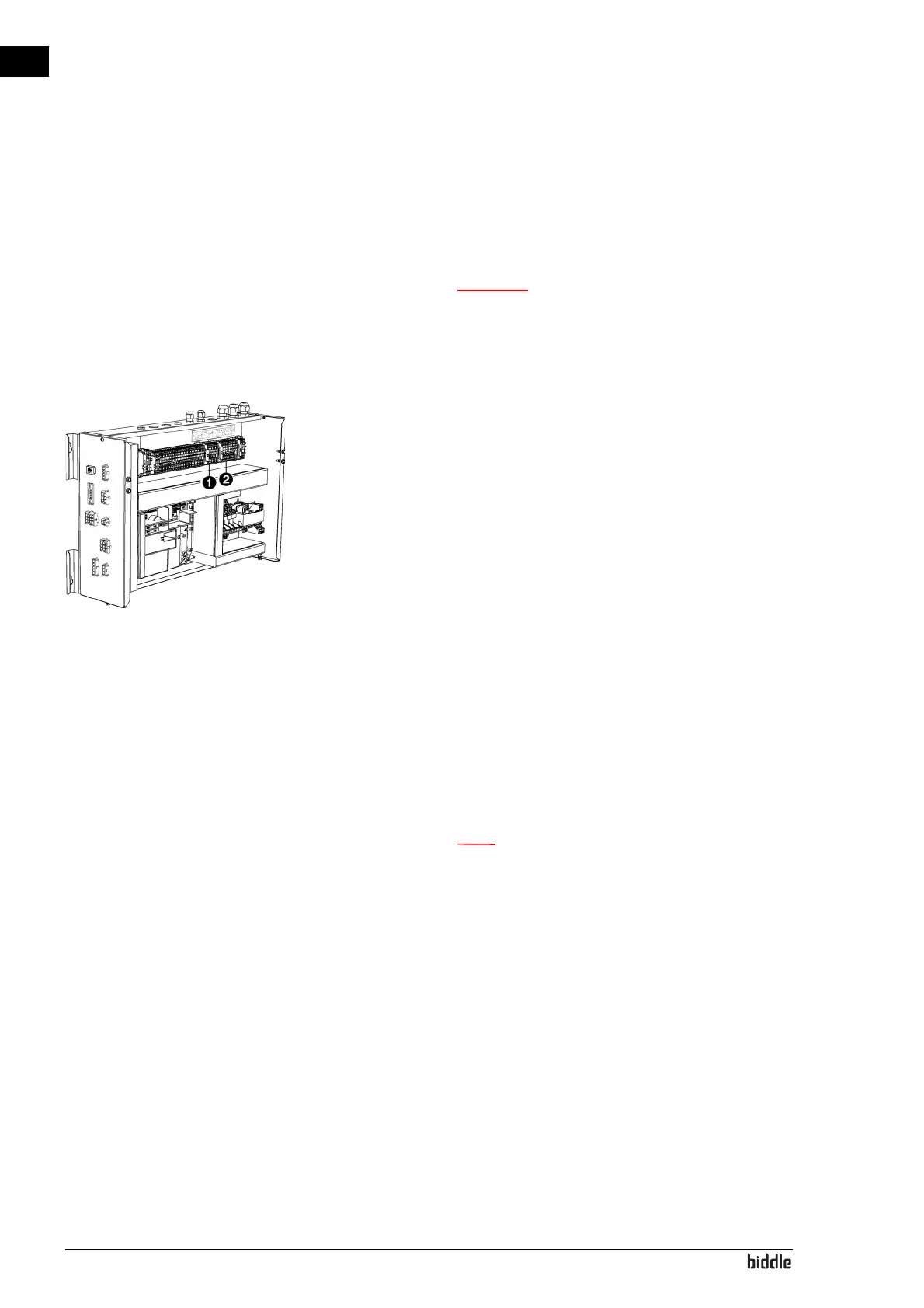
2. Without using the power supply (230V) from the unit:
- Connect the sensor to X3 1 in the electronics mod-
ule in accordance with the wiring diagram
3. Using the power supply (230V) from the unit:
- Connect the sensor to X1 2 in the electronics mod-
ule in accordance with the wiring diagram
- Place a bridge between X1 and X3
n When starting the unit, indicate what response must
be given to a signal from the sensor. (Via the b-touch
control panel: menu > Configuration > 60. Function
of inputs or via the building management system:
register address 337 Alarm functions)