16
July 2020
Installation, Operation and Maintenance Manual
MAN616_EAC Rev. 5
Section 2: Installation
Installation
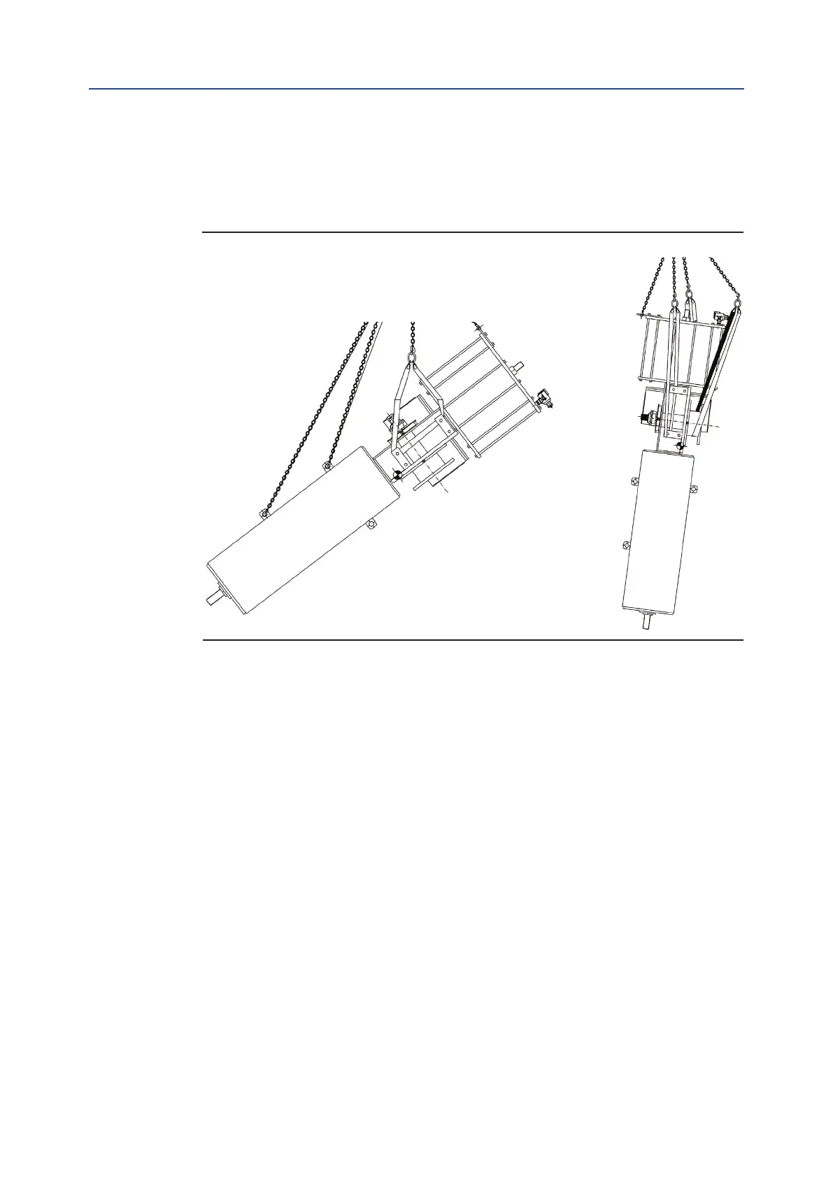
Figure 11 PLAS MHP Without Control System
2. Balance the weight and lift the actuator until to make possible the rotation of
actuator in its nal mounting position, with cylinder on top, or spring container
placed on top, as showed in the following images:
3. Clean the actuator ange and remove anything that might prevent a perfect
adherence to the valve ange and especially all traces of grease.
4. Lift the actuator near to the valve in such a way that the insert bush, assembled
on the valve stem, enters the actuator drive sleeve without forcing the coupling.
When the insert bush has entered the actuator drive sleeve, check the holes of
the valve ange. If they do not meet with the holes of the actuator ange or the
stud bolts screwed into them, the actuator drive sleeve must be rotated; feed the
actuator cylinder with air at proper pressure, indicated on data-sheet for actuator.
5. Tighten the nuts of the connecting stud bolts evenly with the torque prescribed in
the table. The stud bolts must be made of ASTM A320 L7 steel; the nuts must be
made of ASTM A194 grade 2 steel.
6. If possible, operate the actuator to check that it moves the valve smoothly.