18
July 2020
Installation, Operation and Maintenance Manual
MAN616_EAC Rev. 5
Section 3: Operation and Use
Operation and Use
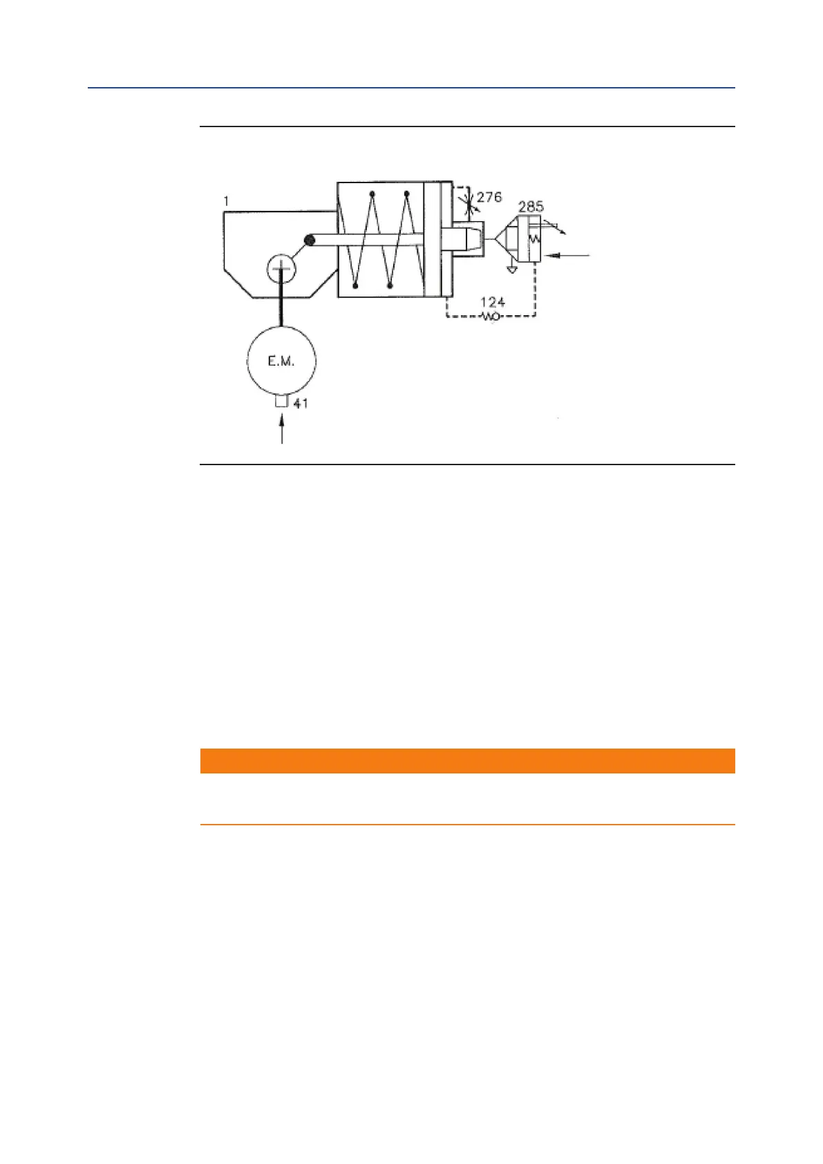
Figure 13 Generic Operating Diagram
1 single acting spring-return pneumatic actuator
41 electric micro-switches
124 check valve
276 bidirectional ow regulator (adjustable setting)
285 adjustable quick exhaust valve with external pilot
Pneumatic Control to Open
Pressurize permanently the pneumatic supply line.
Pneumatic Control to Close
De-pressurize the pneumatic supply line.
The air is exhausted from the cylinder through the quick exhaust valve 285 and the
actuator moves quickly in closing.
Note: the closing time is adjustable by the setting screw on valve 285.
3.2 Residual Risks
!
WARNING
The actuator has parts under pressure. Use the due caution.
Use individual protections provided for by the laws and provisions in force.
3.3 Operations
The operations are carried out sending the proper signal through the control system in
compliance with Customer specications.
Please refer to the functional diagram and specic documentation supplied.
Pneumatic supply connection
Electric connection with micro-switches