17
Installation, Operation and Maintenance Manual
MAN616_EAC Rev. 5 July 2020
Section 3: Operation and Use
Operation and Use
Section 3: Operation and Use
3.1 Operation Description
The actuator is operated by:
1. Pressurized motor uid.
2. Elastic return of compression helicoidally spring.
In the rst case the alimentation uid pressurizes a chamber of the cylinder and
compresses the spring (Figure 13); this determines the linear motion of the piston
and the consequent rotation motion of the scotch yoke mechanism to which valve stem
is coupled.
The uid contained in the other chamber is discharged through the return line.
In the second case, cutting off or in case of lack of pressure to the cylinder and
to the pilot of the fast discharge valve, the opening of the latter is determined,
the fast discharge of motor uid, the quick extension of the spring and the consequent
fast operation of the actuator. The motor uid going out from one chamber of the cylinder
partially returns in the other chamber and partially ows through the discharge line.
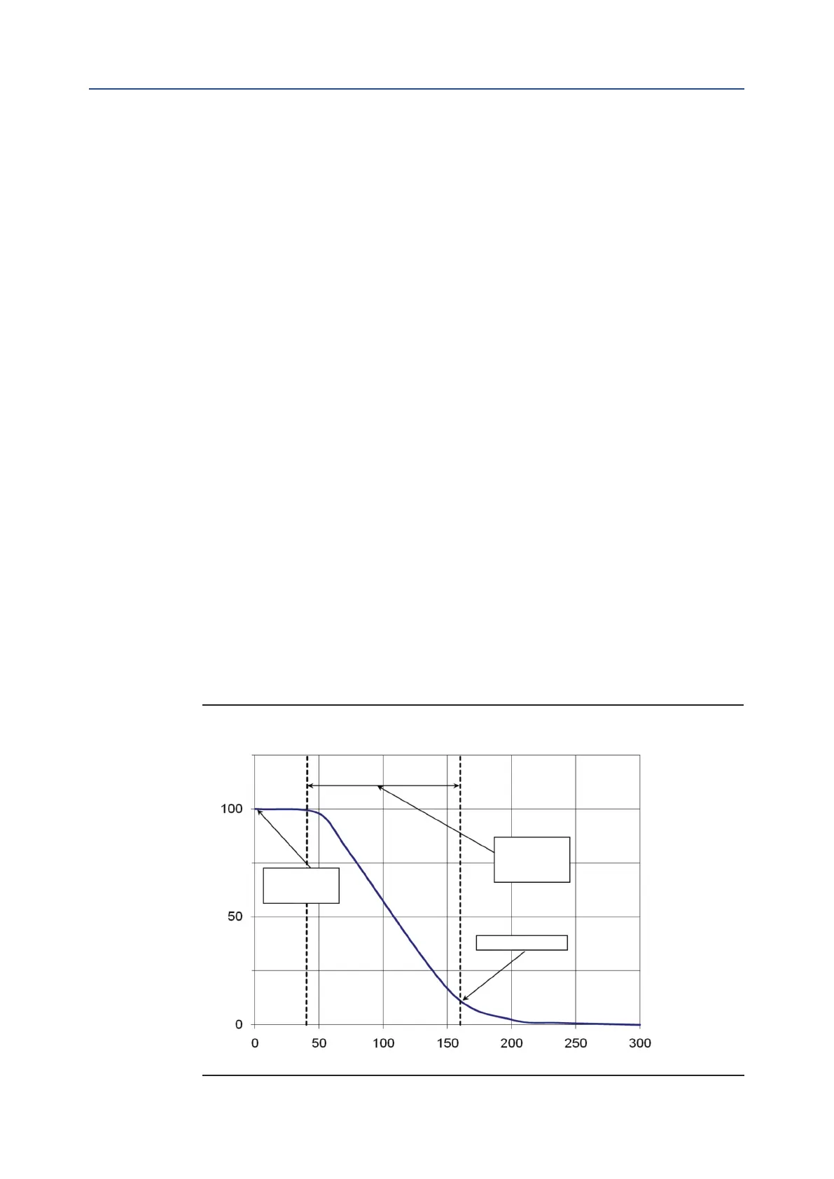
The last part of the cylinder stroke is strongly slowed down by a damper with 2 by-pass
system that throttles the outlet of the motor uid. Figure 12 shows the diagram angular
stroke/time. By-pass action must be regulate to make more slowly the last part of cylinder
stroke (see Section 3.4.1).
The power and control systems are supplied on specic customer demand.
For the relevant information please refer to the specic documentation supplied.
Angular stroke %
Time (ms)
Quick operation
signal
Quick operation
time
Damper action
Figure 12 Angular Stroke/Quick Operation Time Diagram